Toyota Sienna 2010-2026 Owners Manual: Automatic door locking and unlocking systems
The following functions can be set or cancelled: For instructions on customizing, refer to
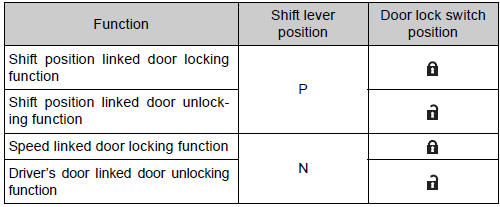
| Function | Operation |
| Shift position linked door locking function | Shifting the shift lever out of P locks all the doors |
| Shift position linked door unlocking function | Shifting the shift lever to P unlocks all the doors. |
| Speed linked door locking function | All the doors are locked when the vehicle speed is approximately 12 mph (20 km/h) or higher. |
| Driver’s door linked door unlocking function | Vehicles without a smart key system:
All the doors are unlocked when the driver’s
door is opened within approximately 45 seconds
after turning the engine switch to “ACC”
or “LOCK”.
Vehicles with a smart key system: All the doors are unlocked when the driver’s door is opened within approximately 45 seconds after turning the engine switch off. |
Setting and canceling the functions
To switch between set and canceled, follow the procedure below:
- Close all the doors and turn the engine switch to the “ON” position (vehicles without a smart key system) or IGNITION ON mode (vehicles with a smart key system). (Perform step 2 within 10 seconds.)
- Shift the shift lever to P or N,
and press and hold the door
lock switch (
 or
or
 ) for
) for
approximately 5 seconds and then release.The shift lever and switch positions corresponding to the desired function to be set are shown in the following table.
Use the same procedure to cancel the function.

When the setting or canceling operation is complete, all the doors are locked and then unlocked.
Switching the door unlock function (vehicles with a smart key system)
It is possible to set which doors the entry function unlocks using the wireless remote control.
- Turn the engine switch off.
- When the indicator on the key surface is not on, press and hold
 ,
,
 ,
,
 ,
,
 or
or
 for about 5 seconds while
pressing and holding .
.
The setting changes each time an operation is performed, as shown below.
(When changing the setting continuously, release the buttons, wait for at least 5 seconds, and repeat step 2.)
|
Multi-information display |
Unlocking function |
Beep |
|
|
Holding the driver’s door handle unlocks only the driver’s door and driver side power sliding door. | Exterior: Beeps three
times Interior: Pings once |
| Holding the front passenger’s door handle or pulling either power sliding door handle unlocks all doors. | ||
|
|
Holding either front door handle or pulling either power sliding door handle unlocks all doors | Exterior: Beeps twice Interior: Pings once |


For vehicles equipped with an alarm, to prevent unintended triggering of the
alarm, unlock the doors using the wireless remote control and open and close
a door once after the settings have been changed. (If a door is not opened
within 60 seconds after is pressed,
the doors will be locked again and
the alarm will automatically be set.)
In case that the alarm is triggered, immediately stop the alarm.
When all the doors are locked with the wireless remote control or key
The doors cannot be unlocked with the door lock switch.
The door lock switch can be reset by unlocking all the doors with the wireless remote control or key.
Using the mechanical key (vehicles with a smart key system)
The doors can also be locked and unlocked with the mechanical key.
Conditions affecting the operation of the smart key system or wireless remote control
- Vehicles without a smart key system
The wireless remote control function may not operate normally in the following situations:
- Near a TV tower, radio station, electric power plant, airport or other facility that generates strong radio waves
- When carrying a portable radio, cellular phone or other wireless communication devices
- When multiple wireless keys are in the vicinity
- When the wireless key is in contact with, or is covered by, a metallic object
- When a wireless key (that emits radio waves) is being used nearby
- When the wireless key has been left near an electrical appliance such as a personal computer
- If window tint with a metallic content or metallic objects is attached to the rear window
- Vehicles with AUTO ACCESS SEAT: If the wireless remote control of the
AUTO ACCESS SEAT is operated simultaneously, the AUTO ACCESS
SEAT may not operate properly.
For details, refer to “AUTO ACCESS SEAT OWNER’S MANUAL”.
- Vehicles with a smart key system The smart key system uses weak radio waves. In the following situations, the communication between the electronic key and the vehicle may be affected, preventing the smart key system and wireless remote control from operating properly. (Way of coping )
- When the electronic key battery is depleted
- Near a TV tower, electric power plant, gas station, radio station, large display, airport or other facility that generates strong radio waves or electrical noise
- When carrying a portable radio, cellular phone, cordless phone or other wireless communication devices
- When the electronic key is in contact with, or is covered by the following objects
- Cards to which aluminum foil is attached
- Cigarette boxes that have aluminum foil inside
- Metallic wallets or bags
- Coins
- Hand warmers made of metal
- Media such as CDs and DVDs
- When multiple electronic keys are in the vicinity
- When another wireless key (that emits radio waves) is being used nearby
- When carrying or using the electronic key together with the following devices that emit radio waves
- Another vehicle’s electronic key
- A wireless key that emits radio waves
- Personal computers or personal digital assistants (PDAs)
- Digital audio players
- Portable game systems
- If window tint with a metallic content or metallic objects are attached to the rear window
- Vehicles with AUTO ACCESS SEAT: If the wireless remote control of the
AUTO ACCESS SEAT is operated simultaneously, the AUTO ACCESS
SEAT may not operate properly.
For details, refer to “AUTO ACCESS SEAT OWNER’S MANUAL”.
Customization
Settings (e.g. unlocking function using a key) can be changed.
(Customizable features: )
| WARNING To prevent an accident Observe the following precautions while driving the vehicle. Failing to do so may result in a door opening and an occupant falling out, resulting in death or serious injury.
|
 Locking the front doors from the outside without a key
Move the inside lock button to the lock position.
Close the door.
Vehicles without a smart key system
The doors cannot be locked if either of the front doors is open and the
key is in t ...
 Sliding doors
Vehicles without power sliding doors
The sliding doors can be opened and closed using the sliding
door handle. The sliding door can be locked and unlocked using
the wireles ...
Other materials:
No Signal from Transmitter ID1
DESCRIPTION
The tire pressure warning valve and transmitters that are installed in the
tire and wheel assemblies
measure the air pressure of the tires. The measured values are transmitted to
the tire pressure warning
antenna and receiver on the body as radio waves and then sent to the tir ...
ECM Power Source Circuit
DESCRIPTION
When the ignition switch is turned to the ON position, the battery voltage is
applied to terminal IGSW of
the ECM. The ECM MREL output signal causes a current to flow to the coil,
closing the contacts of the EFI
relay and supplying power to terminal +B of the ECM.
If the igniti ...
Removal
1. REMOVE REAR SEAT LEG SIDE GARNISH SUBASSEMBLY RH
Disengage the clips and remove the seat leg side
garnish sub-assembly RH.
2. REMOVE REAR NO. 2 SEAT ASSEMBLY RH
Remove the bolt and locus cable RH.
Remove the 2 bolts and rear No. 2 seat assembly
RH.
R ...
