Toyota Sienna 2010-2026 Owners Manual: Child restraint systems with a top tether strap (third seat)
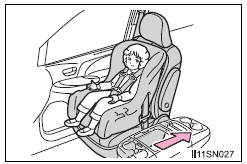
Center seat
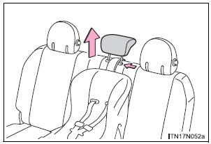
- Secure the child restraint system using the seat belt or LATCH anchors. Adjust the head restraint to the uppermost position.

- Latch the hook onto the
anchor bracket and tighten
the top tether strap.
Make sure the top tether strap is securely latched.
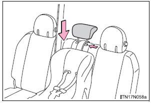
- Adjust the head restraint to the downmost position.
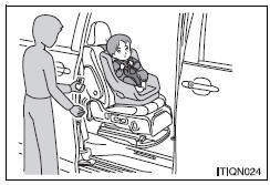
Right outboard seat
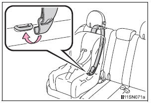
Latch the hook onto the anchor bracket and tighten the top tether strap.
Make sure the top tether strap is securely latched.
Pull the head restraint up to use.
Laws and regulations pertaining to anchorages
The LATCH system conforms to FMVSS225 or CMVSS210.2.
Child restraint systems conforming to FMVSS213 or CMVSS213 specifications can be used.
This vehicle is designed to conform to the SAE J1819.
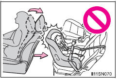
| WARNING When installing a booster seat To prevent the belt from going into ALR lock mode, do not fully extend the shoulder belt. ALR mode causes the belt to tighten only. This could cause injury or discomfort to the child. When installing a child restraint system Follow the directions given in the child restraint system installation manual and fix the child restraint system securely in place. If the child restraint system is not correctly fixed in place, the child or other passengers may be seriously injured or even killed in the event of sudden braking, sudden swerving or an accident.
When installing a child restraint system
When installing a child restraint system to the AUTO ACCESS SEAT (if equipped)
Do not use a seat belt extender If a seat belt extender is used when installing a child restraint system, the seat belt will not securely hold the child restraint system, which could cause death or serious injury to the child or other passengers in the event of sudden braking, sudden swerving or an accident. To correctly attach a child restraint system to the anchors When using the LATCH anchors, be sure that there are no foreign objects around the anchors and that the seat belt is not caught behind the child restraint system. Make sure the child restraint system is securely attached, or it may cause death or serious injury to the child or other passengers in the event of a sudden braking, sudden swerving or an accident. |

 Child restraint systems with a top tether strap (second seat)
Secure the child restraint system
using the seat belt or
LATCH anchors, and adjust the
head restraint to the uppermost
position.
*: Ottoman seat only
Latch the hook onto t ...
 Exhaust gas precautions
Harmful substance to the human body is included in exhaust
gases if inhaled.
WARNINGExhaust gases include harmful carbon monoxide (CO),
which is colorless and
odorless. Observe the fol ...
Other materials:
Data list / active test
1. USING INTELLIGENT TESTER
Connect the intelligent tester to the DLC3.
Monitor the ECU data by following the prompts on
the tester screen.
HINT:
The intelligent tester has a "Snapshot" function
which records the monitored data.
Refer to the intelligent tester o ...
Installation with LATCH system (second seat)
Fold the seatback while pulling
the lever and move to the rearmost
recline position.
Widen the gap between the seat cushion and seatback slightly.
Type A
Latch the hooks of the lower
straps onto the LATCH
anchors. If the child restraint
has a top tether strap, the ...
Registration
1. DESCRIPTION OF CODE REGISTRATION
HINT:
The key has 2 codes: The key code (immobiliser code)
and the wireless code. Both of these codes need to be
registered. Refer to page for the wireless code
registration procedures.
When adding master keys or sub keys (Additional
registration) ...
