Toyota Sienna Service Manual: Data list / active test
1. DATA LIST
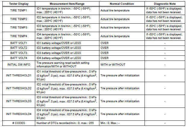
HINT: Using the intelligent tester to read the DATA LIST allows the values or states of switches, sensor, actuators and other items to be read without removing any parts. This non-intrusive inspection can be very useful because intermittent conditions or signals may be discovered before parts or wiring is disturbed. Reading the DATA LIST information early in troubleshooting is one way to save diagnostic time.
NOTICE: In the table below, the values listed under "Normal Condition" are reference values. Do not depend solely on these reference values when deciding whether a part is faulty or not
(a) Make sure that the ignition switch is off.
(b) Connect the intelligent tester to DLC3.
(c) Turn the ignition switch to the ON position.
(d) Following the display on the intelligent tester, read "DATA LIST".
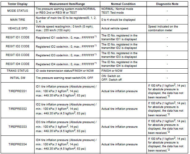
HINT: *1: Displayed only when the ID No. is not registered.
*2: It may take about 5 to 6 minutes until the values are displayed. If the values are not displayed after a few minutes, perform troubleshooting according to the inspection procedure for DTCs C2121/21 to C2124/24 (See page TW-42)
METER:
2. ACTIVE TEST
Using the intelligent tester to perform ACTIVE TEST allows the meters, indicators and other items to be operated without removing any parts. Performing ACTIVE TEST early in troubleshooting is one way to save diagnostic time. It is possible to display the DATA LIST on the intelligent tester during ACTIVE TEST.
(a) Make sure that the ignition switch is off.
(b) Connect the intelligent tester to the DLC3.
(c) Turn the ignition switch to the ON position.
(d) Enter the following menus: DIAGNOSIS / OBD/ MOBD / METER / ACTIVE TEST.
METER:
 Dtc check / clear
1. DTC CHECK (USING SST CHECK WIRE)
(a) Check DTCs.
(1) Turn the ignition switch off.
(2) Using SST, connect terminals TC and CG of
DLC3.
SST 09843-18040
(3) Turn the ignition switch to ...
 Diagnostic trouble code chart
HINT:
If a trouble code is displayed during the DTC check, inspect
the circuit listed for that code. For details of each code, refer
to the relevant page listed under respective "DTC No." ...
Other materials:
Distance Control ECU Power Source Circuit
DESCRIPTION
This circuit provides power to operate the distance control ECU. The distance
control ECU determines
information about the vehicle in front based on data from the laser sensor, and
then decides how much
acceleration and/or deceleration is needed to maintain the set distance. The
...
Camera Picture Error
DTC 5C-40 Camera Picture Error
DESCRIPTION
DTC No.
DTC Detection Condition
Trouble Area
5C-40
Synchronous signal from the camera cannot be
transmitted.
Wire harness
Television camera assembly
Radio and navigation assembly
...
Air conditioning filter
The air conditioning filter must be changed regularly to maintain
air conditioning efficiency
Removal method
Turn the engine switch to the “LOCK” position (vehicles without a
smart key system) or off (vehicles with a smart key system).
Open the glove box. Slide off
the damper.
...
