Toyota Sienna Service Manual: Dtc check / clear
1. DTC CHECK (USING SST CHECK WIRE)
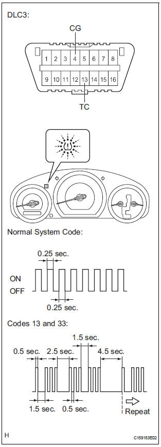
(a) Check DTCs.
(1) Turn the ignition switch off.
(2) Using SST, connect terminals TC and CG of DLC3.
SST 09843-18040
(3) Turn the ignition switch to the ON position.
(4) Read and record any DTCs from the tire pressure warning light on the combination meter.
Refer to the illustration as examples of a normal system code and codes 13 and 33.
HINT:
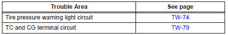
- If the tire pressure warning light does not
indicate any DTCs or the normal system
code, inspect the tire pressure warning light
circuit or TC and CG terminal circuit.
- If 2 or more malfunctions are indicated at the same time, the lowest numbered DTC is displayed first.
(5) Refer to the Diagnostic Trouble Code Chart (See page TW-37) for DTC information.
(6) After completing the check, turn the ignition switch off and remove SST from DLC3.
SST 09843-18040
2. DTC CHECK (USING INTELLIGENT TESTER)
(a) Check DTCs.
(1) Make sure that the ignition switch is off.
(2) Connect the intelligent tester to the DLC3.
(3) Turn the ignition switch to the ON position.
(4) Read the DTCs following the prompts on the tester screen.
HINT: Refer to the intelligent tester operator's manual for further details.
(b) Clear the DTCs.
HINT: After repairing the malfunctions, clear the DTCs.
(1) Make sure that the ignition switch is off.
(2) Connect the intelligent tester to DLC3.
(3) Turn the ignition switch to the ON position.
(4) Clear the DTCs following the prompts on the tester screen.
HINT: Refer to the intelligent tester operator's manual for further details.
 Diagnosis system
1. CHECK BATTERY VOLTAGE
Standard voltage:
11 to 14 V
If the voltage is below 11 V, recharge the battery before
proceeding.
2. CHECK DLC3
(a) The ECU uses the ISO 15765-4 for communication
pr ...
 Data list / active test
1. DATA LIST
HINT:
Using the intelligent tester to read the DATA LIST allows
the values or states of switches, sensor, actuators and
other items to be read without removing any parts. This
non-in ...
Other materials:
Front Airbag Sensor LH Circuit Malfunction
DTC B1149/37 Front Airbag Sensor LH Circuit Malfunction
DESCRIPTION
The front airbag sensor LH circuit consists of the center airbag sensor
assembly and front airbag sensor
LH.
If the center airbag sensor assembly receives signals from the front airbag
sensor LH, it judges whether or
not ...
Removal
1. REMOVE V-BANK COVER SUB-ASSEMBLY (See
page EM-28)
2. REMOVE NO. 1 ENGINE UNDER COVER (See page
EM-26)
3. DRAIN ENGINE COOLANT (See page CO-6)
4. REMOVE FRONT WHEEL RH
5. REMOVE FRONT FENDER APRON SEAL RH
6. REMOVE V-RIBBED BELT (See page EM-6)
7. DISCONNECT NO. 2 RADIATOR HOSE
(a) Di ...
Entire Combination Meter does not Operate
DESCRIPTION
This is the power source circuit to operate the combination meter assembly.
WIRING DIAGRAM
INSPECTION PROCEDURE
1 INSPECT COMBINATION METER ASSEMBLY
Disconnect the C10 connector.
Measure the resistance according to the value(s) in the
table below.
Standard resistan ...
