Toyota Sienna Service Manual: Differential system
PRECAUTION
NOTICE:
When disconnecting the negative (-) battery terminal, initialize the following systems after the terminal is reconnected.
1. Before disassembly, clean the outside of the rear differential assembly and remove any sand or mud to prevent it from entering the inside of the assembly during disassembly and reassembly.
2. When removing a connected part made of light alloy such as a rear differential carrier cover, tap it off with a plastic hammer. Do not attempt to pry it off with a screwdriver.
3. Always arrange disassembled parts in order and protect them from dust.
4. Before reassembly, thoroughly clean and dry each part or then apply hypoid gear oil LSD to it. Do not use alkaline cleaner for aluminum or rubber parts and ring gear set bolts. Also, do not clean rubber parts such as O-rings or oil seals with non residue solvent.
5. Coat any sliding surface and rotating part with hypoid gear oil LSD.
6. When holding a component part in a vise, be sure to place an aluminum sheet under the part. Do not put it directly on the vise.
7. Be careful not to damage the contact surfaces of the case. Such damage may cause oil leakage.
8. Before applying sealant, remove deposited oil sealant and clean the part to be sealed using non residue solvent.
9. Do not apply oil immediately after installing sealed parts. Leave it for at least an hour.
10.Damage on the surface of an oil seal, O-ring or gasket may cause oil leakage.
11.When press-fitting an oil seal, be careful not to damage the oil seal lip and outside periphery.
12.When replacing a bearing, replace the inner and outer races as a set.
PROBLEM SYMPTOMS TABLE
HINT: Use the table below to help you find the cause of the problem.
The numbers indicate the priority of the likely cause of the problem. Check each part in order. If necessary, replace these parts.
DIFFERENTIAL SYSTEM: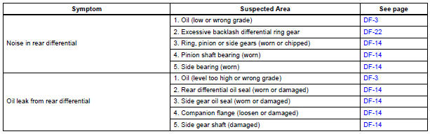
 Differential
...
 Differential oil
Adjustment
1. INSPECT DIFFERENTIAL OIL
(a) Stop the vehicle on the level place.
(b) Remove the differential filler plug and gasket.
(c) Check that the oil surface is within 5 mm (0.20 in.) ...
Other materials:
Oil and oil filter
COMPONENTS
REPLACEMENT
CAUTION:
Prolonged and repeated contact with engine oil will
result in the removal of natural oils from the skin,
leading to dryness, irritation and dermatitis. In
addition, used engine oil contains potentially harmful
contaminants which may caus ...
Ignition Switch Circuit
DESCRIPTION
When the ignition switch is turned to the ON position, battery positive
voltage is applied to terminal IG of
the ECU. When battery positive voltage is applied to terminal IG of the ECU
while the theft deterrent
system is operating, the warning stops.
WIRING DIAGRAM
INSPECTIO ...
Removal
1. PRECAUTION
CAUTION:
Be sure to read "PRECAUTION" thoroughly before
servicing.
2. DISCONNECT CABLE FROM NEGATIVE BATTERY
TERMINAL
CAUTION:
Wait for 90 seconds after disconnecting the cable to
prevent the airbag working.
3. REMOVE FRONT SEAT ASSEMBLY (for Manual Seat)
4. REMOVE ...
