Toyota Sienna Service Manual: Washer Signal Circuit
DESCRIPTION
The distance control ECU detects washer operation. The cruise control will be cancelled by the distance control ECU if the windshield wipers operate in the HI or LO mode. By detecting washer operation, the distance control ECU allows the cruise control to continue even when the windshield wipers operate in the HI or LO mode.
WIRING DIAGRAM
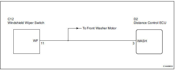
INSPECTION PROCEDURE
1 INSPECT WASHER SYSTEM
- Check that the front washer operates.
OK: Washer function is normal.
2 CHECK HARNESS AND CONNECTOR (DISTANCE CONTROL ECU - WINDSHIELD WIPER SWITCH)
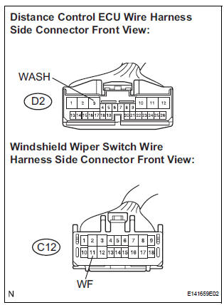
- Disconnect the D2 distance control ECU connector and C12 windshield wiper switch connector.
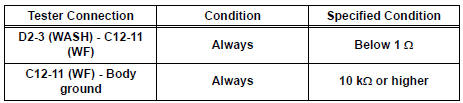
- Measure the resistance according to the value(s) in the table below.
Standard resistance
PROCEED TO NEXT CIRCUIT INSPECTION SHOWN IN PROBLEM SYMPTOMS TABLE
 Wiper Signal Circuit
DESCRIPTION
The distance control ECU detects wiper operation. If the windshield wipers
operate in the HI or LO mode,
the cruise control is canceled and the warning sound "pong" is emitte ...
 Cruise Main Indicator Light Circuit
DESCRIPTION
When the cruise control main switch is on, the CRUISE main indicator light
and READY indicator light
come on. This indicates the control condition (presence or absence of a vehicle
i ...
Other materials:
Installation
1. Install torque converter clutch assembly
(a) Install the torque converter clutch to the automatic
transaxle.
(b) Using vernier calipers and a straight edge, measure
the dimension "A" between the transaxle fitting part
of the engine and the converter fitting part of the
drive ...
Diagnostic trouble code chart
If a DTC is displayed during the DTC check, check the parts
listed in the table below and proceed to the page given.
HINT:
*1: Comes on MIL (Malfunction Indicator Lamp) light up
*2: "DTC stored" mark means ECM memorizes the
malfunction code if the ECM detects the DTC detection
...
Noise Occurs from Generator while Engine is Running
INSPECTION PROCEDURE
1 CHECK LOOSENESS OF V-RIBBED BELT
(a) Check the tension of the belt by pushing it down with a
finger.
OK:
The tension of the belt is enough.
2 CHECK V-RIBBED BELT FOR WEAR
(a) Check the V-ribbed belt for wear.
OK:
The V-ribbed belt is not worn.
3 CHECK CLUTC ...
