Toyota Sienna Service Manual: Disassembly
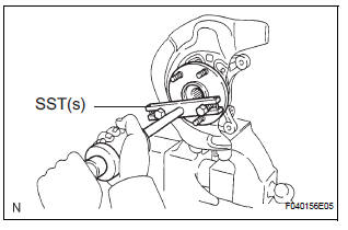
1. REMOVE LOWER BALL JOINT ASSEMBLY FRONT LH
(a) Remove the cotter pin and nut.
(b) Using SST(s), remove the lower ball joint assembly front LH.
SST 09628-62011
2. REMOVE FRONT WHEEL BEARING DUST DEFLECTOR NO.1 LH
(a) Using a screwdriver, remove the bearing dust deflector NO. 1 LH.
3. REMOVE FRONT AXLE HUB LH HOLE SNAP RING
(a) Using snap ring pliers, remove the front axle hub LH hole snap ring.
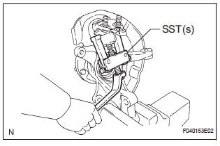
4. REMOVE FRONT AXLE ASSEMBLY LH
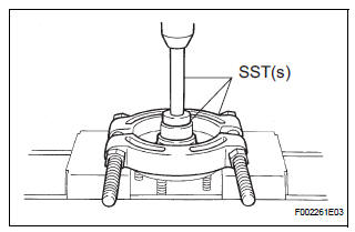
(a) Using SST(s), remove the front axle hub subassembly LH.
SST 09520-00031
(b) Using SST(s) and a press, remove the bearing inner race (outside) from the front axle hub sub-assembly LH.
SST 09950-00020, 09950-60010 (09951-00430), 09950-70010 (09951-07100)
5. REMOVE DISC BRAKE DUST COVER FRONT LH
(a) Using a torx wrench (T30), remove the 4 bolts and disc brake dust cover front LH.
HINT: Torx is a registered trademark of Textron Inc.
6. REMOVE FRONT AXLE HUB LH BEARING
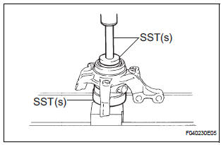
(a) Place the bearing inner race (outside) on the front axle hub LH bearing.
(b) Using SST(s) and a press, press the front axle hub LH bearing until it contacts the SST(s).
SST 09527-17011, 09950-60010 (09951-00600), 09950-70010 (09951-07100)
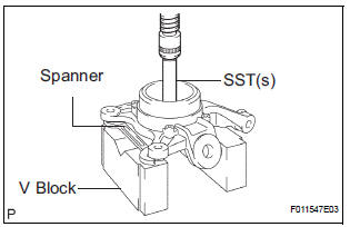
(c) Using a spanner to make the steering knuckle LH horizontal, fix it to the V block, as shown in the illustration.
NOTICE: Be sure the steering knuckle is horizontally positioned.
(d) Using SST(s) and a press, remove the front axle hub LH bearing.
SST 09950-60010 (09951-00600), 09950-70010 (09951-07100)
 Removal
HINT:
Replace the RH side using the same procedures as for the
LH side.
1. REMOVE FRONT WHEEL
2. REMOVE FRONT AXLE HUB LH NUT (See page DS-
5)
3. SEPARATE SPEED SENSOR FRONT LH (See page
DS-5)
...
 Reassembly
1. INSTALL FRONT AXLE HUB LH BEARING
(a) Using SST(s) and a press, install a new front axle
hub LH bearing to the steering knuckle LH.
SST 09950-60020 (09951-00810), 09950-70010
(09951-07100 ...
Other materials:
Access monitor result
(A) select the following menus on the intelligent tester:
diagnosis, enhanced obdii, monitor info
and monitor result. The monitor status
appears after the component name.
INCMP: The component has not been monitored
yet.
PASS: The component is functioning normally.
FAIL: The component is ...
Installation
1. INSTALL NO.1 NAVIGATION BRACKET
Install the No.1 navigation bracket with the 4
screws.
2. INSTALL NO.2 NAVIGATION BRACKET
Install the No.2 navigation bracket with the 4
screws.
3. INSTALL INSTRUMENT CLUSTER FINISH PANEL UPPER
Install the instrum ...
Brake Warning Light does not Come ON
WIRING DIAGRAM
See page BC-52.
INSPECTION PROCEDURE
1 INSPECT BRAKE WARNING LIGHT
(a) Disconnect the skid control ECU connector.
(b) Turn the ignition switch to the on position.
(c) Check that the BRAKE warning light comes on.
OK:
BRAKE warning light comes on.
HINT:
If troubleshooting ...
