Toyota Sienna Service Manual: Removal
HINT: Replace the RH side using the same procedures as for the LH side.
1. REMOVE FRONT WHEEL
2. REMOVE FRONT AXLE HUB LH NUT (See page DS- 5)
3. SEPARATE SPEED SENSOR FRONT LH (See page DS-5)
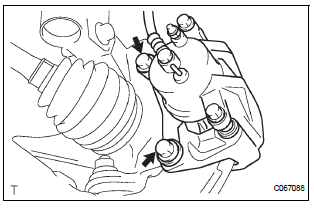
4. SEPARATE FRONT DISC BRAKE CALIPER ASSEMBLY LH

(a) Remove the 2 bolts and separate the front disc brake caliper assembly LH from the steering knuckle LH.
NOTICE: Use a string or other device to keep the brake caliper from hanging down.
5. REMOVE FRONT DISC
6. SEPARATE TIE ROD END SUB-ASSEMBLY LH (See page DS-6)
7. SEPARATE FRONT SUSPENSION ARM SUBASSEMBLY LOWER NO.1 LH (See page DS-6)
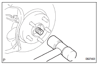
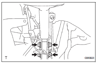
8. REMOVE FRONT AXLE ASSEMBLY LH

(a) Using a plastic hammer, separate the front drive shaft assembly LH from the front axle hub subassembly LH.
NOTICE: Be careful not to damage the boot and ABS speed sensor rotor.

(b) Remove the 2 bolts, nuts and steering knuckle LH with the front axle nub sub-assembly LH.
 On-vehicle inspection
1. INSPECT FRONT AXLE HUB BEARING BACKLASH
(a) Using a dial gauge, check for backlash near the
center of the axle hub.
Maximum:
0.05 mm (0.0020 in.)
If backlash exceeds the maximum, replace t ...
 Disassembly
1. REMOVE LOWER BALL JOINT ASSEMBLY FRONT LH
(a) Remove the cotter pin and nut.
(b) Using SST(s), remove the lower ball joint assembly
front LH.
SST 09628-62011
2. REMOVE FRONT WHEEL BEAR ...
Other materials:
Short to GND in Rear Curtain Shield Squib LH
Circuit
DTC B1637/85 Short to GND in Rear Curtain Shield Squib LH
Circuit
DESCRIPTION
The rear curtain shield squib LH circuit consists of the center airbag sensor
assembly and the curtain
shield airbag assembly LH.
The circuit instructs the SRS to deploy when deployment conditions are met.
DTC ...
Diagnosis system
1. CHECK BATTERY VOLTAGE
Standard voltage:
11 to 14 V
If the voltage is below 11 V, recharge the battery before
proceeding.
2. CHECK DLC3
(a) The ECU uses the ISO 15765-4 for communication
protocol. The terminal arrangement of the DLC3
complies with SAE J1962 and matches the ISO
15765-4 f ...
On-vehicle inspection
1. INSPECT BRAKE PEDAL HEIGHT
(a) Check the brake pedal height.
Pedal height from dash panel:
150.3 to 160.3 mm (5.917 to 6.311 in.)
NOTICE:
Do not adjust the pedal height. Doing so by
changing the push rod length will structurally
change the pedal ratio.
2. CHECK AND ADJUST STOP LIGHT S ...
