Toyota Sienna Service Manual: Reassembly
1. INSTALL FRONT AXLE HUB LH BEARING
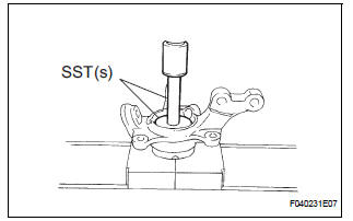
(a) Using SST(s) and a press, install a new front axle hub LH bearing to the steering knuckle LH.
SST 09950-60020 (09951-00810), 09950-70010 (09951-07100)
2. INSTALL DISC BRAKE DUST COVER FRONT LH
(a) Place the disc brake dust cover front LH and using a torx wrench (T30), torque the 4 bolts.
Torque: 8.3 N*m (85 kgf*cm, 74 in.*lbf)
HINT: Torx is a registered trademark of Textron Inc.
3. INSTALL FRONT AXLE HUB SUB-ASSEMBLY LH
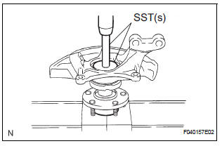
(a) Using SST(s), and a press, install the front axle hub sub-assembly LH.
SST 09608-32010, 09950-60020 (09951-00810), 09950-70010 (09951-07100)
4. INSTALL FRONT AXLE HUB LH HOLE SNAP RING
(a) Using snap ring pliers, install a new front axle hub LH hole snap ring.
5. INSTALL FRONT WHEEL BEARING DUST DEFLECTOR NO.1 LH
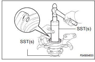
(a) Using SST(s) and a hammer, install the bearing dust deflector No. 1 LH.
SST 09316-60011 (09316-00011, 09316-00031), 09608-32010
HINT: Align the hole for the speed sensor in the bearing dust deflector No. 1 LH with the steering knuckle.
6. INSTALL LOWER BALL JOINT ASSEMBLY FRONT LH
(a) Install the lower ball joint assembly front LH and tighten the nut.
Torque: 123 N*m (1,250 kgf*cm, 91 ft.*lbf) (b) Install a new cotter pin.
NOTICE: If the holes for the cotter pin are not aligned, tighten the nut up to 60° further.
 Disassembly
1. REMOVE LOWER BALL JOINT ASSEMBLY FRONT LH
(a) Remove the cotter pin and nut.
(b) Using SST(s), remove the lower ball joint assembly
front LH.
SST 09628-62011
2. REMOVE FRONT WHEEL BEAR ...
 Installation
1. INSTALL FRONT AXLE ASSEMBLY LH
(a) Install the 2 bolts, nuts and front axle assembly LH
with the 2 bolts and nuts to the shock absorber
assembly front LH.
Torque: 230 N*m (2,350 kgf*cm, 170 ...
Other materials:
Removal
1. REMOVE FRONT WHEEL
2. REMOVE FRONT AXLE HUB LH NUT
HINT:
(See page AH-4)
SST 09930-00010
3. SEPARATE SPEED SENSOR FRONT LH
HINT:
(See page AH-4)
4. SEPARATE FRONT DISC BRAKE CALIPER
ASSEMBLY LH
HINT:
(See page AH-4)
5. REMOVE FRONT DISC
6. SEPARATE TIE ROD ASSEMBLY LH
HINT:
(See pa ...
Camshaft Position "B" Actuator Circuit
DESCRIPTION
The Variable Valve Timing (VVT) system includes the ECM, OCV and VVT
controller. The ECM sends a
target duty-cycle control signal to the OCV. This control signal regulates the
oil pressure supplied to the
VVT controller. Camshaft timing control is performed according to engine ...
DTC check / clear
1. USING INTELLIGENT TESTER
Hook up the intelligent tester to the DLC3.
Monitor the ECU data by following the prompts on
the tester screen.
HINT:
intelligent tester has "Snapshot" function which
records the monitored data. Please refer to the
intelligent tester op ...
