Toyota Sienna 2010-2026 Owners Manual: Display contents
The multi-information display presents the driver with a variety of vehicle data.
- Menu icons
Displays the following information when an icon is selected.
Some of the information may be displayed automatically depending on the situation.
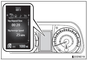
 Drive information
Select to display various drive data.
 Navigation system-linked display
(if equipped)
Select to display the following navigation system-linked information.
- Route guidance
- Compass display (north-up display/heading-up display)
 Audio system-linked display
Select to enable selection of an audio source or track on the meter using the meter control switches.
 Cruise control display (if
equipped)
Select to display the information and operation procedures of the cruise control.
 Dynamic radar cruise control
display (if equipped)
Select to display the information and operation procedures of the
dynamic radar cruise control.
The  tab will change to
 when the vehicle is in constant
speed control mode.
 Warning message display
Select to display warning messages and measures to be taken if a malfunction is detected.
 Settings display
Select to change the meter display settings.
- Intuitive parking assist display (if equipped)
Automatically displayed when the system is used

 Operating the meter control switches
The multi-information display is
operated using the meter control
switches.
Enter/Set
Select an item/Change pages
Return to the previous screen
Press: Displays the screen registered
...
Other materials:
Screen Flicker or Color Distortion
INSPECTION PROCEDURE
1 CHECK DISPLAY SETTING
Enter the display adjustment screen by pressing the
"DISPLAY" switch.
Reset display settings (contrast, brightness) and check
that the screen appears normal
Press the "INFO" switch and then select "S ...
Panel Switches do not Function
INSPECTION PROCEDURE
1 CHECK PANEL SWITCH
Check for foreign matter around the switches that might
prevent operation.
OK:
No foreign matter is found
2 CHECK PANEL SWITCH (DISPLAY CHECK MODE)
Enter the "Display Check" mode (Panel Switch Check).
Operate the abnorma ...
General information
A large number of ECU controlled systems are used in the
SIENNA. In general, ECU controlled systems are considered
to be very intricate, requiring a high level of technical
knowledge to troubleshoot. However, most problem checking
procedures only involve inspecting the ECU controlled
system's c ...
