Toyota Sienna Service Manual: Door control transmitter
INSPECTION
1. INSPECT DOOR CONTROL TRANSMITTER
- Inspect operation of the transmitter.
- Remove the battery (lithium battery) from the transmitter.
- Install a new or normal battery (lithium battery).
- When a new or normal battery is not available, connect 2 new 1.5 V batteries in series, connect the battery positive (+) to the battery receptacle side terminal and battery negative (- ) to the bottom terminal, then apply 3 V voltage to the transmitter.
- In a location that is approx. 1m (3.28 ft) away from the driver side outside door handle in the right direction, point the key plate of the transmitter at the vehicle and check operation of the transmitter by pressing a transmission switch on the transmitter body.
Standard: The door lock can be operated via the remote control.
HINT:
- The minimum operational distance differs, depending on the operator, the way the transmitter is held, and the location.
- Since the transmitter uses faint electric waves, the operational distance might be shortened if noise or strong electric wave occurs in the area where the frequency is used.
- Install the battery (lithium battery).
- Inspect the battery capacity.
HINT:
- The capacity of the battery can be determined only when the battery is installed in the transmitter. For a lithium battery used in the transmitter, a voltage of more than 2.5 V is shown on the tester until the energy is completely consumed, while no battery is installed in the transmitter. Therefore, it is necessary to measure the voltage while the battery is installed in transmitter (a resistance of 1.2 kΩ is applied to the battery) when checking the amount of energy left in the battery.
- If the transmitter is faulty, the amount of energy left in the battery might not be checked correctly.
- Remove the battery (lithium battery) from the transmitter.
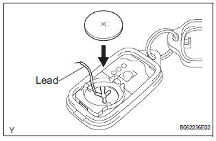
- Connect the lead to the negative (-) terminal of the transmitter and install the battery.
- Connect the tester positive (+) probe to the positive (+) battery (lithium battery) and the tester negative (-) probe to the lead respectively.
- Press one of the transmission switches on the transmitter for approx. 1 second.
- Press the transmission switch on the transmitter again to check the voltage.
Standard voltage: 2.2 V or higher
HINT:
- When the temperature of the battery is low,
the inspection can not be made correctly.
When the outcome of the test is less than 2.2 V, conduct the test again after leaving the battery in a place at 18C (64F) for more than 30 minutes.
- The automatic power-off function causes the voltage of the battery to be 2.5 V or more (a voltage with no resistance applied to the battery) when 0.8 seconds have passed after the switch is pressed. Therefore, make sure to read the voltage just after the switch is pressed.
- Since high voltage might be shown once or twice after the battery returns to the specified temperature, the inspection should be made with the voltage shown after the switch is pressed at least 3 times.
- Disconnect the lead.
- Set the battery (lithium battery) in the transmitter.
 Transmitter battery
REPLACEMENT
1. REMOVE TRANSMITTER BATTERY
NOTICE:
Special caution should be taken for handling each
component as they are precision electronic
components.
Using a coin or the equiva ...
 Door control switch
INSPECTION
1. INSPECT DOOR CONTROL SWITCH ASSEMBLY
Measure the resistance according to the value(s) in
the table below.
Standard resistance
HINT:
If the result is not as spec ...
Other materials:
Inspection
1. INSPECT REAR SPEED SENSOR
(a) Disconnect the skid control sensor connector.
(b) Measure the resistance between terminals 1 and 2
of the skid control sensor connector.
OK:
Resistance:
less than 2.2 kΩ
(c) Measure resistance between each of terminals 1
and 2 of the skid control s ...
Wireless remote control/
electronic key battery
Replace the battery with a new one if it is depleted.
You will need the following items:
Flathead screwdriver
Lithium battery CR2032
Replacing the battery
Vehicles without a smart key system
Remove the cover using a coin
protected with tape etc.
Remove the deplete ...
Removal
1. REMOVE REAR DOOR SCUFF PLATE LH
2. REMOVE REAR DOOR WEATHERSTRIP LH
3. REMOVE BACK DOOR WEATHERSTRIP
4. REMOVE BACK DOOR SCUFF PLATE
5. REMOVE QUARTER TRIM FRONT PANEL ASSEMBLY LH
6. REMOVE POWER POINT SOCKET ASSEMBLY
Release the 2 claw fittings and remove the power
point soc ...
