Toyota Sienna Service Manual: Operating Light Control Rheostat does not Change Light Brightness
DESCRIPTION
The meter CPU receives signals for adjusting illumination on the meter from this circuit. The meter CPU detects the illumination level selected by the user according to the position of the rheostat knob.
WIRING DIAGRAM
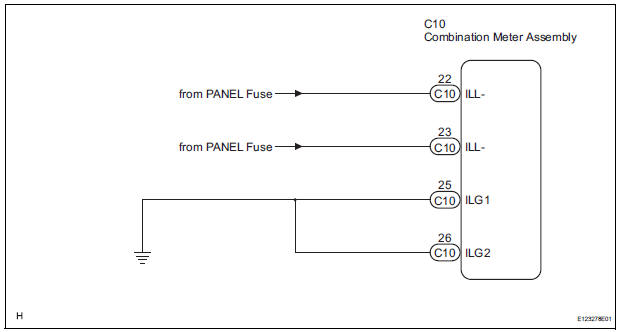
INSPECTION PROCEDURE
1 READ VALUE OF INTELLIGENT TESTER (LIGHT RHEOSTAT)
- Connect the intelligent tester to the DLC3.
- Turn the switch to the ON position.
- Turn the tester ON.
- Enter the following menus: DIAGNOSIS / OBD/MOBD / METER / DATA LIST.
- Check the values by referring to the table below.
METER:
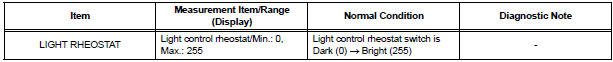
OK: Light brightness displayed on the tester is almost the same as the actual light brightness.
REPLACE COMBINATION METER ASSEMBLY
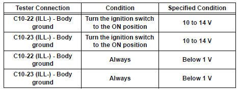
2 CHECK HARNESS AND CONNECTOR (LIGHT CONTROL RHEOSTAT CIRCUIT)
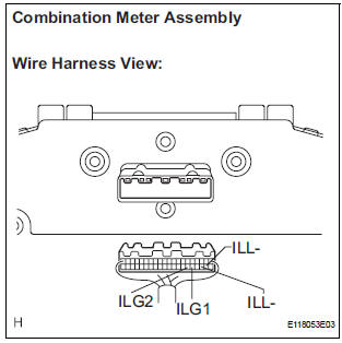
- Disconnect the C10 connectors.
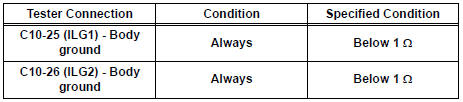
- Measure the resistance according to the value(s) in the table below.
Standard resistance
- Measure the voltage according to the value(s) in the table below.
Standard voltage
REPLACE COMBINATION METER ASSEMBLY
 Driver Side Seat Belt Warning Light does not Operate
DESCRIPTION
When turning the ignition switch to the ON position, the combination meter
assembly communicates with
the supplemental restraint system by the multiplex communication system. Unless
...
 Meter Illumination is Always Dark
DESCRIPTION
Confirm that the vehicle is equipped with the optitron meter, then
check this circuit.
The combination meter assembly receives a auto dimmer signal from the
body ECU by t ...
Other materials:
Installation
1. INSTALL 3 POINT TYPE NO. 2 REAR SEAT BELT ASSEMBLY
Check the degree of tilt when the belt begins to lock
the ELR.
Check that the belt does not lock within 15 of
tilt in all directions but that the belt locks with
over 45 of tilt, when gently moving the
retractor. ...
Reassembly
1. INSTALL RACK STEERING PISTON RING
(a) Coat a new O-ring with power steering fluid and
install it onto the power steering rack.
(b) Expand a new rack steering piston ring with your
fingers.
NOTICE:
Be careful not to over expand the rack steering
piston ring.
(c) Coat a new rack steer ...
Reassembly
1. INSTALL SHOCK ABSORBER ASSEMBLY FRONT LH
2. INSTALL FRONT COIL SPRING INSULATOR LOWER
LH
(a) Install the front coil spring insulator lower LH onto
the shock absorber assembly front LH.
3. INSTALL FRONT SPRING BUMPER LH
(a) Install the front spring bumper LH to the piston rod.
4. INSTALL FR ...
