Toyota Sienna 2010-2026 Owners Manual: Engine immobilizer system
The vehicle’s keys have built-in transponder chips that prevent the engine from starting if a key has not been previously registered in the vehicle’s on-board computer.
Never leave the keys inside the vehicle when you leave the vehicle.
This system is designed to help prevent vehicle theft but does not guarantee absolute security against all vehicle thefts.
- Vehicles without a smart key system
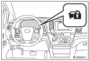
The indicator light flashes after the key has been removed from the engine switch to indicate that the system is operating.
The indicator light stops flashing after the registered key has been inserted into the engine switch to indicate that the system has been canceled.
- Vehicles with a smart key system
The indicator light flashes after the engine switch has been turned off to indicate that the system is operating.
The indicator light stops flashing after the engine switch has been turned to ACCESSORY or IGNITION ON mode to indicate that the system has been canceled.
System maintenance
The vehicle has a maintenance-free type engine immobilizer system.
Conditions that may cause the system to malfunction
- If the grip portion of the key is in contact with a metallic object
- If the key is in close proximity to or touching a key to the security system (key with a built-in transponder chip) of another vehicle
Certifications for the engine immobilizer system
- For vehicles sold in the U.S.A.
Vehicles without a smart key system FCC ID: WRKRI-34BTY Vehicles with a smart key system FCC ID: NI4TMIMB-1 This device complies with part 15 of the FCC Rules. Operation is subject to the following two conditions: (1) This device may not cause harmful interference, and (2) this device must accept any interference received, including interference that may cause undesired operation.
Changes or modifications not expressly approved by the party responsible for compliance could void the user’s authority to operate the equipment.
- For vehicles sold in Canada
This device complies with Industry Canada licence-exempt RSS standard(s).
Operation is subject to the following two conditions: (1) this device may not cause interference, and (2) this device must accept any interference, including interference that may cause undesired operation of the device.
| NOTICE To ensure the system operates correctly Do not modify or remove the system. If modified or removed, the proper operation of the system cannot be guaranteed. |

 Alarm
Alarm
...
Other materials:
Rear wiper motor and bracket
COMPONENTS
REMOVAL
1. REMOVE REAR WIPER ARM
Remove the rear wiper arm head cap from the rear
wiper arm.
Remove the nut and the rear wiper arm.
2. REMOVE BACK DOOR GARNISH CENTER
3. REMOVE BACK DOOR SIDE GARNISH LH
4. REMOVE POWER BACK DOOR ROD
5. REMOVE BACK DOOR ...
How to proceed with
troubleshooting
1 VEHICLE BROUGHT INTO A WORKSHOP
2 DIAGNOSTIC QUESTIONING AND SYMPTOM CONFIRMATION
Ask the customer about symptoms and confirm
malfunctions.
3 CONFIRM THE SYSTEM NORMAL CONDITION
4 CHECK DTC
HINT:
If the system cannot enter the diagnosis mode, inspect each
AVC-LAN communication signal ...
No. 1 Clearance Warning Buzzer Circuit
DESCRIPTION
The clearance warning ECU receives the ultrasonic sensor signal to sound the
front warning buzzer.
WIRING DIAGRAM
INSPECTION PROCEDURE
1 INSPECT FRONT BUZZER
Remove the clearance warning ECU with front buzzer.
Apply the battery voltage to the terminals 1 and 2 o ...
