Toyota Sienna Service Manual: Rear wiper motor and bracket
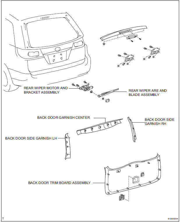
COMPONENTS
REMOVAL
1. REMOVE REAR WIPER ARM
- Remove the rear wiper arm head cap from the rear wiper arm.
- Remove the nut and the rear wiper arm.
2. REMOVE BACK DOOR GARNISH CENTER
3. REMOVE BACK DOOR SIDE GARNISH LH
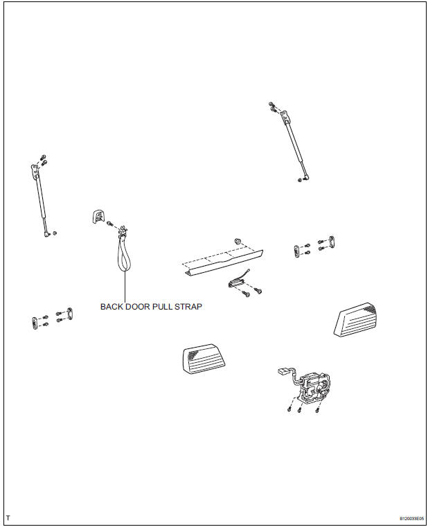
4. REMOVE POWER BACK DOOR ROD
5. REMOVE BACK DOOR SIDE GARNISH RH
6. REMOVE BACK DOOR STRAP COVER
7. REMOVE BACK DOOR TRIM BOARD ASSEMBLY
8. REMOVE REAR WIPER MOTOR AND BRACKET ASSEMBLY
- Remove the 3 bolts.
- Disconnect the connector, and remove the rear wiper motor assembly.
INSPECTION
1. INSPECT REAR WIPER MOTOR AND BRACKET ASSEMBLY
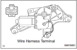
- Operation check
- Connect the battery (+) to the terminal 1 (+B) of the connector, the battery (-) to the terminal 3 (LS) of the connector and wire harness terminal of the rear wiper motor and bracket assembly, then check that the rear wiper motor and bracket operate.
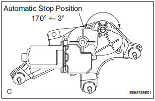
- Automatic Stop Position Operation Check
- Connect the battery (+) to the terminal 1 (+B) of
the connector, the battery (-) to the terminal 3
(LS) of the connector and wire harness terminal
of the rear wiper motor and bracket assembly.
With the motor being rotated disconnect the terminal 3 (LS) from the battery (-), then check that the wiper motor stops automatically to the automatic stop position
INSTALLATION
1. INSTALL REAR WIPER MOTOR AND BRACKET ASSEMBLY
- Install the rear wiper motor assembly with the 3
bolts.
Torque: 5.5 N*m (56 kgf*cm, 49 in.*lbf)
- Connect the connector.
2. INSTALL REAR WIPER ARM
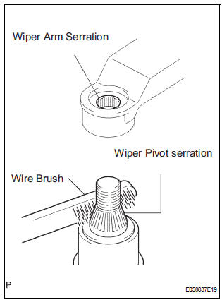
- Scrape off the serration part of the wiper arm with a round file or equivalent.
- Clean the rear wiper pivot serration with a brush.
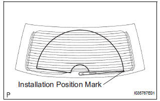
- Stop the rear wiper motor assembly to the automatic
stop position. Install the rear wiper arm to the
position as shown in the illustration.
Torque: 5.5 N*m (56 kgf*cm, 49 in.*lbf)
- Install the rear wiper arm head cap.
 Front wiper rubber
COMPONENTS
REMOVAL
1. REMOVE FRONT WIPER BLADE
Remove the front wiper blade from the front wiper
arm LH.
NOTICE:
Do not fold down the front wiper arm with the
front wiper blade ...
 Rear wiper rubber
COMPONENTS
REMOVAL
1. REMOVE REAR WIPER BLADE ASSEMBLY
Remove the rear wiper arm head cap from the rear
wiper arm.
Raise the rear wiper blade to the position as shown
i ...
Other materials:
Maintenance
requirements
To ensure safe and economical driving, day-to-day care and regular
maintenance are essential. It is the owner’s responsibility to
perform regular checks. Toyota recommends the following maintenance:
General maintenance
General maintenance should be performed on a daily basis. This can
be done ...
Removal
1. Disconnect cable from negative battery
terminal
2. REMOVE STEERING COLUMN COVER LOWER
(A) insert the key into the ignition key cylinder and
release the steering lock.
(B) turn the steering wheel clockwise to gain access to
the screw and remove the screw.
(c) Turn the steering whe ...
Installation
1. INSTALL AIR CONDITIONING BLOWER ASSEMBLY
(a) Install the air conditioning blower assembly with the
3 bolts.
Torque: 5.4 N*m (55 kgf*cm, 48 in.*lbf)
NOTICE:
Tighten the bolts in the order shown in the
illustration to install the air conditioning blower
assembly.
2. INSTALL AIR CONDITIO ...
