Toyota Sienna Service Manual: No. 1 Clearance Warning Buzzer Circuit
DESCRIPTION
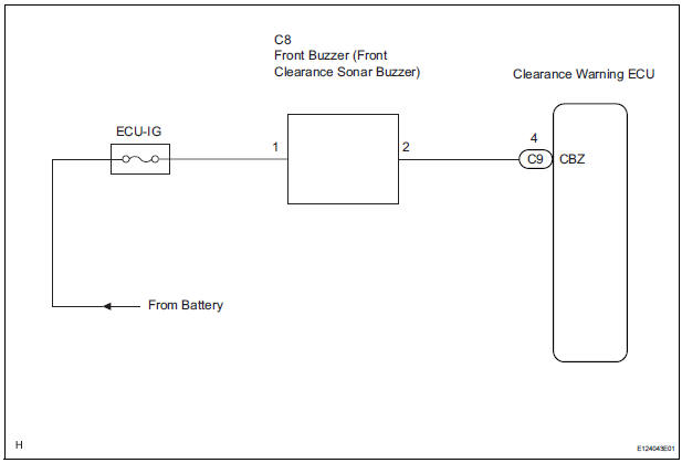
The clearance warning ECU receives the ultrasonic sensor signal to sound the front warning buzzer.
WIRING DIAGRAM
INSPECTION PROCEDURE
1 INSPECT FRONT BUZZER
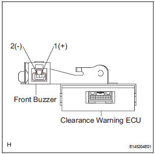
- Remove the clearance warning ECU with front buzzer.
- Apply the battery voltage to the terminals 1 and 2 of the buzzer, and check that the buzzer sounds.
HINT: The clearance warning buzzer is separately excited, and will not sound unless an alternating voltage is applied.
OK: Operating noise (clicking sounds) can be heard.
2 CHECK HARNESS AND CONNECTOR (CLEARANCE WARNING ECU - FRONT BUZZER)
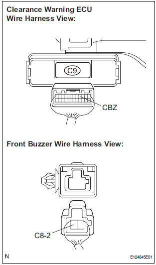
- Disconnect the clearance warning ECU connector and front buzzer connector.
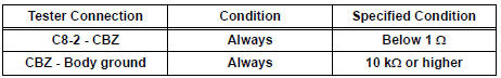
- Measure the resistance according to the value(s) in the table below.
Standard resistance
PROCEED TO NEXT CIRCUIT INSPECTION SHOWN IN PROBLEM SYMPTOMS TABLE
 Rear Clearance Sonar Sensor RH Circuit
DESCRIPTION
An ultrasonic sensor consists of a sensor portion that transmits and receives
ultrasonic waves and a preamplifier
that amplifies them. The ultrasonic sensor outputs the ultrasonic wave ...
 Clearance Warning ECU Power Source Circuit
DESCRIPTION
This circuit provides power to the clearance warning ECU.
WIRING DIAGRAM
INSPECTION PROCEDURE
1 CHECK HARNESS AND CONNECTOR (CLEARANCE WARNING ECU - AIR CONDITIONER
AMPLIFIER)
...
Other materials:
Actuator Supply Voltage Circuit / Open
DTC P0657 Actuator Supply Voltage Circuit / Open
DESCRIPTION
The ECM monitors the output voltage to the throttle actuator. This self-check
ensures that the ECM is
functioning properly. The output voltage is usually 0 V when the ignition switch
is turned off. If the output
voltage is higher t ...
Power easy access system
The seat is automatically adjusted to allow the driver to enter and exit
the vehicle easily.
When all of the following have
been performed, the driver’s seat
is automatically adjusted to a
position that allows driver to enter
and exit the vehicle easily.
The shift lever has been sh ...
Oxygen Sensor Heater Control Circuit
HINT:
Sensor 2 refers to the sensor mounted behind the Three-Way Catalytic
Converter (TWC) and located
furthest from the engine assembly.
DESCRIPTION
Refer to DTC P0136 (See page ES-160).
HINT:
When any of these DTCs are set, the ECM enters fail-safe mode. The ECM turns
off the Heated ...
