Toyota Sienna Service Manual: MIL Circuit
DESCRIPTION
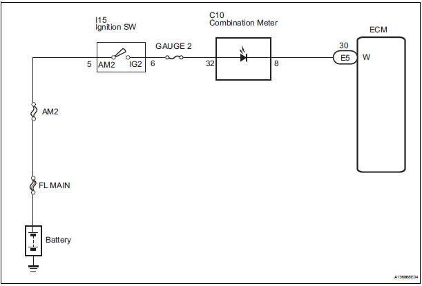
The MIL (Malfunction Indicator Lamp) is used to indicate vehicle malfunctions detected by the ECM.
When the ignition switch is turned to the ON position, power is supplied to the MIL circuit, and the ECM provides the circuit ground which illuminates the MIL.
The MIL operation can be checked visually. When the ignition switch is first turned to the ON position, the MIL should be illuminated and should then turn off. If the MIL remains illuminated or is not illuminated, conduct the following troubleshooting procedure using the intelligent tester.
WIRING DIAGRAM
INSPECTION PROCEDURE
1 CHECK THAT MIL IS ILLUMINATED
- Turn the ignition switch to the ON position.
- Check the illumination of the MIL.
Result
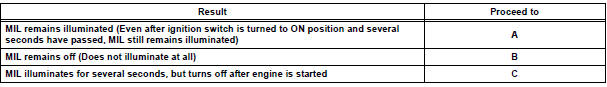
2 CHECK WHETHER MIL TURNS OFF
- Connect the intelligent tester to the DLC3.
- Turn the ignition switch to the ON position and turn the tester on.
- Select the following menu items: DIAGNOSIS / ENHANCED OBD II / DTC INFO / CURRENT CODES.
- Check if any DTCs have been stored. Note down any DTCs.
- Clear the DTCs.
- Check if the MIL goes off.
Standard: MIL goes off.
3 CHECK HARNESS AND CONNECTOR (CHECK FOR SHORT IN WIRE HARNESS)
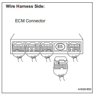
- Disconnect the E5 ECM connector.
- Turn the ignition switch to the ON position.
- Check that the MIL is not illuminated.
OK: MIL is not illuminated.
- Reconnect the ECM connector.
4 CHECK HARNESS AND CONNECTOR (COMBINATION METER - ECM)
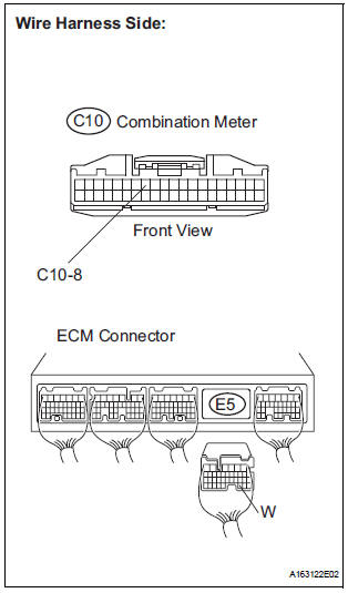
- Disconnect the E5 ECM connector.
- Disconnect the C10 combination meter connector.
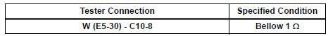
- Measure the resistance according to the value(s) in the table below.
Standard resistance (Check for Open)
Standard resistance (Check for Short)
- Reconnect the ECM connector.
- Reconnect the combination meter connector.
REPAIR OR REPLACE HARNESS OR CONNECTOR (COMBINATION METER - ECM)
5 CHECK THAT ENGINE STARTS
- Turn the ignition switch to the ON position.
- Start the engine.
Result
HINT: *: The intelligent tester cannot communicate with the ECM.
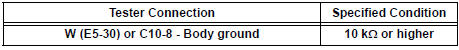
6 CHECK HARNESS AND CONNECTOR (COMBINATION METER - BODY GROUND)
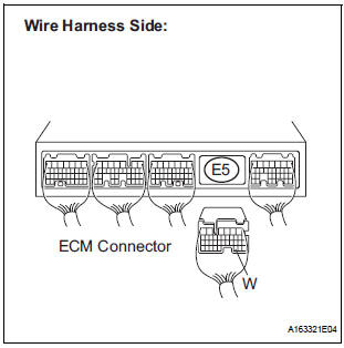
- Disconnect the E5 ECM connector.
- Turn the ignition switch to the ON position.
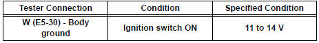
- Measure the voltage according to the value(s) in the table below.
Standard voltage
- Reconnect the ECM connector.
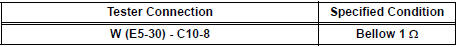
7 CHECK HARNESS AND CONNECTOR (COMBINATION METER - ECM)
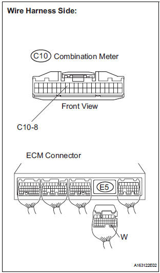
- Disconnect the E5 ECM connector.
- Disconnect the C10 combination meter connector.
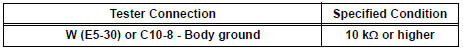
- Measure the resistance according to the value(s) in the table below.
Standard resistance (Check for short)
Standard resistance (Check for Short)
- Reconnect the ECM connector.
- Reconnect the combination meter connector.
REPLACE COMBINATION METER ASSEMBLY
 Air Intake Control Circuit
DESCRIPTION
The air cleaner is equipped with two inlets, one of which is opened or closed
by the Air Intake Control
Valve (AICV). This system reduces intake noise and increases engine power at
l ...

Other materials:
Removal
1. PRECAUTION
CAUTION:
Be sure to read "PRECAUTION" thoroughly before servicing.
2. DISCONNECT CABLE FROM NEGATIVE BATTERY
TERMINAL
CAUTION:
Wait for 90 seconds after disconnecting the cable to
prevent the airbag working.
3. REMOVE FRONT SEAT ASSEMBLY (for Manual Seat)
4. REMOVE F ...
Power Window cannot be Operated by Wireless Operation
DESCRIPTION
When the switch on the transmitter is operated during normal operating
conditions, the
multiplex network body ECU sends a request signal to the master switch and the
regulator switches which
then drive the applicable power window motors.
INSPECTION PROCEDURE
1 CHECK WIRELESS DOO ...
Slide door lock release motor
Inspection
1. INSPECT SLIDE DOOR LOCK RELEASE MOTOR ASSEMBLY LH
Apply battery voltage and inspect operation of the
motor.
OK
If the result is not as specified, replace the motor
assembly.
2. INSPECT SLIDE DOOR LOCK RELEASE MOTOR ASSEMBLY RH
Apply battery voltage and insp ...
