Toyota Sienna Service Manual: Inspection
1. INSPECT PRELOAD
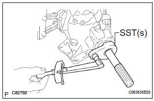
(a) Using SST(s) and a torque wrench, check the initial torque within the backlash range.
SST 09326-20011 Torque: 0.9 to 1.4 N*m (9 to 14 kgf*cm, 8.0 to 12.4 in.*lbf)
HINT: Use a torque wrench with a fulcrum length of 160 mm (6.30 in.).
(b) Using SST(s) and a torque wrench, check the initial torque while the driven pinion is in contact with the ring gear face.
SST 09326-20011 Torque: Preload +0.15 to 0.30 N*m (+1.6 to 3.1 kgf*cm, +1.3 to 2.7 in.*lbf)
HINT: Use a torque wrench with a fulcrum length of 160 mm (6.30 in.).
2. INSPECT DIFFERENTIAL RING GEAR BACKLASH
(a) Set the dial gauge perpendicular to the tooth face of the ring gear, fix the driven pinion and inspect the backlash while moving the gear.
Backlash: 0.10 to 0.15 mm (0.0039 to 0.0059 in.)
NOTICE: Inspect it at 3 points or more on the gear's periphery.
3. INSPECT TOOTH CONTACT BETWEEN RING GEAR AND DRIVE PINION
(a) Apply red lead primer thinly and uniformly to both faces of the ring gear and rotate several times.
NOTICE: Inspect the tooth contact on the ring gear at 4 places or more.
4. INSPECT RUNOUT OF TRANSFER RING GEAR MOUNTING CASE
(a) Using a dial gauge check the transfer ring gear mounting case runout.
Maximum runout: 0.03 mm (0.0012 in.)
 Disassembly
1. REMOVE TRANSFER COVER GASKET
(a) Remove the transfer gasket from the transfer
assembly.
2. REMOVE TRANSFER CASE BREATHER PLUG
(a) Using a screwdriver and a hammer, remove the
transfer ...
 Reassembly
1. INSTALL TRANSFER DRIVEN PINION REAR BEARING
(a) Using SST(s) and a press, install the transfer driven
pinion rear bearing outer race to the transfer case.
SST 09950-60010 (09951-00620), 09950-70 ...
Other materials:
Transmitter ID1 Error
DESCRIPTION
The tire pressure warning valve and transmitters that are installed in the
tire and wheel assemblies
measure the air pressure of the tires. The measured values are transmitted to
the tire pressure warning
antenna and receiver on the body as radio waves and then sent to the tir ...
Communication Error of Yaw Rate Sensor
DTC U0123 Communication Error of Yaw Rate Sensor
DESCRIPTION
This circuit detects the yaw rate of the vehicle and transmits its signal to
the skid control ECU and
distance control ECU.
DTC No.
DTC Detection Condition
Trouble Area
U0123
While the dynamic ...
Door Mirror Foot Light Circuit
DESCRIPTION
When the outer mirror control ECU receives the signal(s) from the body ECU
through BEAN
communication, it illuminates the foot light. The foot light is installed on the
bottom of the outer rear view
mirror and comes on or does off according to the following conditions.
The ligh ...
