Toyota Sienna Service Manual: Installation
1. INSTALL SLIDE DOOR ROLLER ASSEMBLY UPPER
- Apply MP grease to the rotating areas of the roller.
- Install the roller with the 2 bolts.
Torque: 13 N*m (130 kgf*cm, 10 ft.*lbf)
2. INSTALL SLIDE DOOR HINGE ASSEMBLY CENTER LH
- Apply MP grease to the rotating areas of the hinge.
- Install the hinge with the 3 bolts.
Torque: 31 N*m (316 kgf*cm, 23 ft.*lbf)
3. INSTALL SLIDE DOOR ROLLER ASSEMBLY LOWER LH
- Apply MP grease to the rotating areas of the roller.
- Install the roller lower with the 3 bolts.
Torque: 31 N*m (316 kgf*cm, 23 ft.*lbf)
4. INSTALL SLIDE DOOR FULL OPEN STOP LOCK ASSEMBLY LH
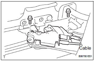
- Apply MP grease to the sliding and rotating areas of the lock.
- Install the lock with the 2 bolts.
Torque: 8.0 N*m (82 kgf*cm, 71 in.*lbf)
- Connect the 2 cables.
5. INSTALL SLIDE DOOR RAILS
- Install the rail center with the 3 screws.
Torque: 26 N*m (265 kgf*cm, 19 ft.*lbf)
- Install the rear side rail with the 2 screws.
Torque: 19.5 N*m (200 kgf*cm, 14 ft.*lbf)
- Install the rail upper with the 2 bolts and 2 nuts.
Torque: 10 N*m (102 kgf*cm, 8 ft.*lbf)
- Install the roof headlining (See page IR-14).
6. INSTALL SLIDE DOOR
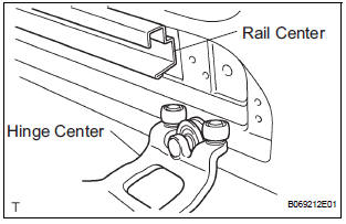
- Put in the slide door hinge center from the rear part of the slide door rail center.
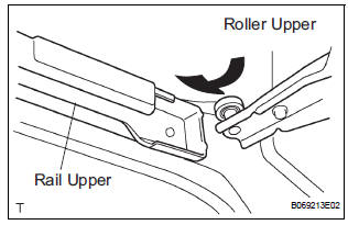
- Move the slide door forward and then put in the slide door roller upper into the cut area of the slide door rail upper
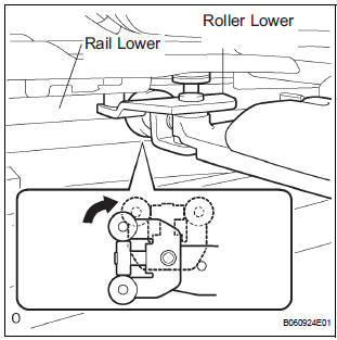
- Rotate the base of the slide door roller lower in the direction indicated by arrow in the illustration and then put in the roller lower into the cut area of the rail lower of the body.
- Install the open stop with the 2 nuts.
Torque: 7.0 N*m (71 kgf*cm, 62 in.*lbf)
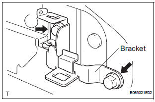
- Install the bracket center No. 2 with the 2 bolts.
Torque: 7.0 N*m (71 kgf*cm, 62 in.*lbf)
- Install the rail end moulding.
- Install the upper rail cushion to the rail upper.
- Install the wire with the bolt.
Torque: 7.0 N*m (71 kgf*cm, 62 in.*lbf)
- Connect the 2 connectors.
7. REPLACE SLIDE DOOR HALF OPEN STOPPER SUBASSEMBLY
- Install the half open stopper with the 2 bolts.
Torque: 7.0 N*m (71 kgf*cm, 62 in.*lbf)
- Connect the control cable to the half open stopper.
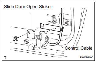
- Connect the control cable to the open striker with
the 2 nuts.
Torque: 7.0 N*m (71 kgf*cm, 62 in.*lbf)
8. REPLACE SLIDE DOOR HALF OPEN STOPPER CONTROL ASSEMBLY
- Install the control cable, as shown in the illustration.
Dimension (A): 3.9 +- 1.5 mm (0.154 +- 0.059 in.)
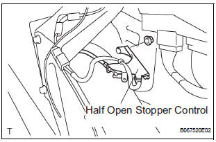
- Install the half open stopper control with the 2 nuts.
Torque: 7.0 N*m (71 kgf*cm, 62 in.*lbf)
9. REPLACE SLIDE DOOR OPEN STRIKER LH
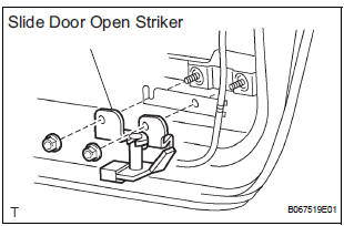
- Install the open striker with the 2 nuts.
Torque: 7.0 N*m (71 kgf*cm, 62 in.*lbf)
10. REPLACE SLIDE DOOR OPEN STRIKER RH
HINT: Use the same procedures for the LH side.
11. REPLACE SLIDE DOOR OPEN STOP LH
- Install the open stop with the 2 nuts.
Torque: 7.0 N*m (71 kgf*cm, 62 in.*lbf)
12. REPLACE SLIDE DOOR OPEN STOP RH
HINT: Use the same procedures for the LH side.
 Reassembly
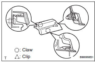
1. INSTALL REAR DOOR WIRE SUB-ASSEMBLY LH
Install the wire.
NOTICE:
When installing the wire, push the areas where
the clips are installed in order to prevent
damage and deformation.
...
 Slide door lock release motor
Inspection
1. INSPECT SLIDE DOOR LOCK RELEASE MOTOR ASSEMBLY LH
Apply battery voltage and inspect operation of the
motor.
OK
If the result is not as specified, replace the motor
as ...
Other materials:
Inspection
1. INSPECT SPEED SENSOR (NT SENSOR)
(a) Disconnect the speed sensor connector from the
transaxle.
(b) Measure the resistance according to the value(s) in
the table below.
AISIN made:
TOYOTA made:
2. INSPECT SPEED SENSOR (NC SENSOR)
(a) Disconnect the speed sensor connector from ...
Touch screen gestures
Operations are performed by touching the screen directly with your
finger.
Operation method
Outline
Main use
Touch
Quickly touch and
release once.
Changing and selecting
various settings.
Drag*
Touch the screen
with your ...
Removal
1. REMOVE REAR SEAT 3 POINT TYPE BELT
ASSEMBLY (for 8-Passenger)
HINT:
Refer to the instructions for disassembly of the rear No. 1
seat assembly (for center seat).
Remove the bolt and rear seat 3 point type belt
assembly.
2. REMOVE REAR SEAT 3 POINT TYPE BELT
ASSEMBLY (for 7-Pass ...
