Toyota Sienna Service Manual: Network gateway ECU
COMPONENTS
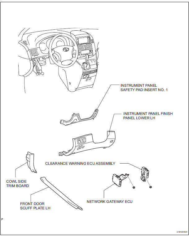
REMOVAL
1. REMOVE FRONT DOOR SCUFF PLATE LH
2. REMOVE COWL SIDE TRIM BOARD LH
3. REMOVE INSTRUMENT PANEL FINISH PANEL LOWER LH (See page IP-6)
4. REMOVE INSTRUMENT PANEL SAFETY PAD INSERT NO. 1 (See page IP-6)
5. REMOVE CLEARANCE WARNING ECU ASSEMBLY (See page PM-15)
6. REMOVE NETWORK GATEWAY ECU
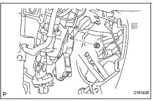
- Disconnect each connector.
- Remove the nut and network gateway ECU.
INSTALLATION
1. INSTALL NETWORK GATEWAY ECU
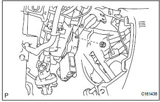
- Install the network gateway ECU with the nut.
- Connect the connector.
2. INSTALL CLEARANCE WARNING ECU ASSEMBLY (See page PM-15)
3. INSTALL PANEL SAFETY PAD INSERT NO. 1
4. REMOVE INSTRUMENT PANEL FINISH PANEL LOWER LH
5. REMOVE COWL SIDE TRIM BOARD LH
6. REMOVE FRONT DOOR SCUFF PLATE LH
 Open in One Side of CAN Branch Line
DESCRIPTION
If 2 or more ECUs and/or sensors do not appear on the intelligent tester
"Communication Bus Check"
screen, one side of the CAN branch wire may be open. (One side of the CAN-H ...
 2Gr-fe ignition
...
Other materials:
Short to B+ in Driver Side Squib Circuit
DTC B0103/12 Short to B+ in Driver Side Squib Circuit
DESCRIPTION
The driver side squib circuit consists of the center airbag sensor assembly,
the spiral cable and the
steering pad.
The circuit instructs the SRS to deploy when deployment conditions are met.
DTC B0103/12 is recorded when a ...
Diagnosis system
1. CHECK DLC3
The vehicle's ECU uses ISO 15765-4 for
communication protocol. The terminal arrangement
of the DLC3 complies with SAE J1962 and matches
the ISO 15765-4 format.
NOTICE:
*: Before measuring the resistance, leave the
vehicle as is for at least 1 minute and do not
...
Inspection
1. V
(a) Inspect VSV operation.
(1) Using an ohmmeter, measure the resistance
according to the value(s) in the table below.V
Standard resistance
If the result is not as specified, replace the
vsv.
(B) inspect the vsv for ground.
(1) Using an ohmmeter, measure the resistance
accordin ...
