Toyota Sienna Service Manual: TS and CG Terminal Circuit
DESCRIPTION
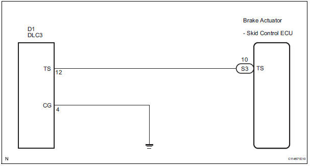
The Test Mode (signal check) circuit detects trouble in the sensor or switch signal, which cannot be detected by the DTC check.
Connecting terminals TS and CG of the DLC3 starts the check.
WIRING DIAGRAM
INSPECTION PROCEDURE
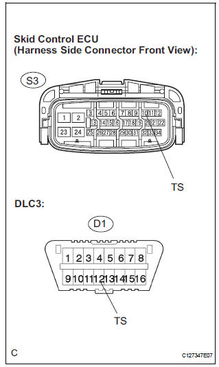
1 CHECK HARNESS AND CONNECTOR (BETWEEN SKID CONTROL ECU AND TS of DLC3)
(a) Turn the ignition switch off.
(b) Disconnect the skid control ECU connector.
(c) Measure the resistance according to the value(s) in the table below.
Standard resistance 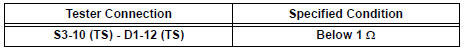

2 CHECK HARNESS AND CONNECTOR (BETWEEN CG of DLC3 AND BODY GROUND)
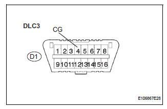
(a) Measure the resistance according to the value(s) in the table below.
Standard resistance

3 CHECK HARNESS AND CONNECTOR (BETWEEN TS of DLC3 AND BODY GROUND)
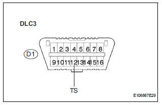
(a) Measure the resistance according to the value(s) in the table below.
Standard resistance 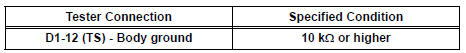

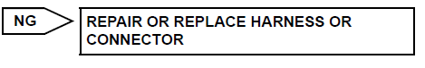
REPLACE BRAKE ACTUATOR ASSEMBLY
 TC and CG Terminal Circuit
DESCRIPTION
DTC output mode is set by connecting terminals TC and CG of the DLC3.
The DTCs are displayed by the blinking pattern of the ABS warning light.
WIRING DIAGRAM
HINT:
When warning ...
 Vehicle stability control system
Parts location
...
Other materials:
Occupant Classification System Malfunction
DTC B1150/23 Occupant Classification System Malfunction
DESCRIPTION
The occupant classification system circuit consists of the center airbag
sensor assembly and the occupant
classification ECU.
If the center airbag sensor assembly receives signals from the occupant
classification ECU, it d ...
Open in Rear Curtain Shield Squib LH Circuit
DTC B1636/88 Open in Rear Curtain Shield Squib LH Circuit
DESCRIPTION
The rear curtain shield squib LH circuit consists of the center airbag sensor
assembly and the curtain
shield airbag assembly LH.
The circuit instructs the SRS to deploy when deployment conditions are met.
DTC B1636/88 ...
Back Door ECU Communication Stop
DTC B1287 Back Door ECU Communication Stop
DESCRIPTION
DTC B1287 is output when communication between the power back door ECU and
the multiplex network
gateway ECU stops for more than 10 seconds.
DTC No.
DTC Detection Condition
Trouble Area
B1287
Back d ...
