Toyota Sienna Service Manual: Open in One Side of CAN Branch Line
DESCRIPTION
If 2 or more ECUs and/or sensors do not appear on the intelligent tester "Communication Bus Check" screen, one side of the CAN branch wire may be open. (One side of the CAN-H [branch wire] / CAN-L [branch wire] of the ECU and/or sensor is open.)
|
Symptom |
Trouble Area |
| 2 or more ECUs and/or sensors do not appear on the intelligent tester "Communication Bus Check" screen. |
|
WIRING DIAGRAM
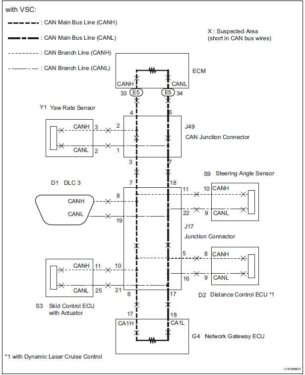
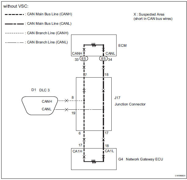
INSPECTION PROCEDURE
NOTICE:
- Turn the ignition switch off before measuring the resistances of CAN bus main wires and CAN bus branch wires.
- After the ignition switch is turned off, check that the key reminder warning system and light reminder warning system are not in operation.
- Before measuring the resistance, leave the vehicle as is for at least 1 minute and do not operate the ignition switch, any other switches, or the doors. If any doors need to be opened in order to check connectors, open the doors and leave them open.
HINT: Perform the following inspection for the ECUs (sensors) which are not displayed on the intelligent tester. If the malfunction cannot be identified, then perform the following inspections for the ECUs (sensors) connected to CAN communication.
1 CHECK FOR OPEN IN ONE SIDE OF CAN BRANCH WIRE
- Confirm the systems (ECUs and sensors), which use CAN communication, equipped on the vehicle. (See page CA-17)
- Using the intelligent tester, select and perform "Communication Bus Check". (See page CA-17) [*1]
- Disconnect the connectors from the ECUs or sensors that are not displayed on the screen. [*2]
- Check that only the ECUs and sensors from which the connectors were disconnected in the previous step are not displayed on the "Communication Bus Check" screen. [*3]
HINT: If any ECUs or sensors, other than those from which the connectors were disconnected in the previous step, are not displayed on the "Communication Bus Check" screen, reconnect the disconnected connectors and repeat the procedures [*1], [*2], and [*3].
(e) Perform the communication stop mode check for the ECUs and sensors which correspond to the disconnected connectors.
GO TO CORRESPONDING COMMUNICATION STOP MODE
 Short to GND in CAN Bus Line
DESCRIPTION
A short to GND is suspected in the CAN bus wire when the resistance between
terminals 4 (CG) and 6
(CANH), or terminals 4 (CG) and 14 (CANL) of the DLC3 is below 200 Ω.
...
 Network gateway ECU
COMPONENTS
REMOVAL
1. REMOVE FRONT DOOR SCUFF PLATE LH
2. REMOVE COWL SIDE TRIM BOARD LH
3. REMOVE INSTRUMENT PANEL FINISH PANEL
LOWER LH (See page IP-6)
4. REMOVE INSTRUMENT PANEL SAFETY PAD
...
Other materials:
Diagnosis system
1. DESCRIPTION
When troubleshooting a vehicle with the diagnosis
system, the only difference from the usual
troubleshooting procedure is connecting the intelligent
tester to the vehicle and reading various data output from
the vehicle's clearance warning ECU.
The clearance warning ECU record ...
Front Occupant Classification Sensor LH Collision
Detection
DTC B1785 Front Occupant Classification Sensor LH Collision
Detection
DESCRIPTION
DTC B1785 is output when the occupant classification ECU receives a collision
detection signal sent by
the front occupant classification sensor LH if an accident occurs.
DTC B1785 is also output when the front ...
Removal
1. REMOVE FRONT DOOR LOWER FRAME BRACKET GARNISH
2. REMOVE FRONT DOOR INSIDE HANDLE BEZEL PLUG
3. REMOVE FRONT DOOR ARMREST BASE PANEL
ASSEMBLY
4. REMOVE BACK FRAME PLATE
5. REMOVE POWER WINDOW REGULATOR MASTER SWITCH ASSEMBLY
6. REMOVE FRONT DOOR TRIM BOARD SUBASSEMBLY
7. REMOVE OUTER RE ...
