Toyota Sienna Service Manual: Open in Occupant Classification ECU Battery Positive Line
DTC B1794 Open in Occupant Classification ECU Battery Positive Line
DESCRIPTION
This circuit consists of the occupant classification ECU and the power source circuit (battery, fuse, wire harness).
DTC B1794 is recorded when a malfunction is detected in the occupant classification ECU or the power source circuit.
HINT: When DTC B1794 is output after switching the ignition switch LOCK-ON-LOCK 50 times in a row when a malfunction occurs in the power circuit for the occupant classification system, the DTC is output again when a malfunction is detected even once after being cleared, unless the normal system code is
|
DTC No. |
DTC Detecting Condition |
Trouble Area |
|
B1794 |
|
|
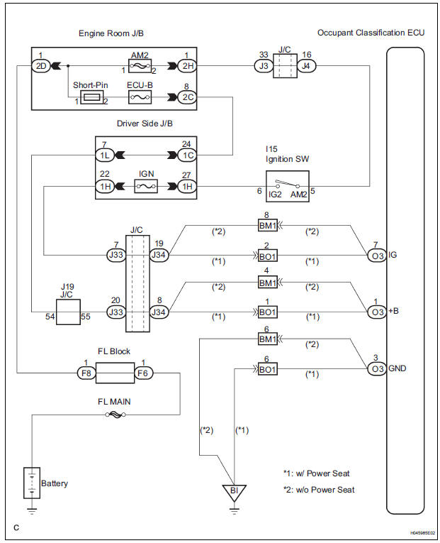
WIRING DIAGRAM
INSPECTION PROCEDURE
1 CHECK BATTERY
- Measure the voltage of the battery.
Standard: 11 to 14 V
2 CHECK FUSE
- Check the ECU-B fuse.
Standard: Below 1 Ω
3 CHECK WIRE HARNESS
- Turn the ignition switch to the LOCK position.
- Disconnect the negative (-) terminal cable from the battery, and wait for at least 90 seconds.
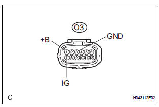
- Disconnect the connector from the occupant classification ECU.
- Connect the negative (-) terminal cable to the battery.
- Turn the ignition switch to the ON position.
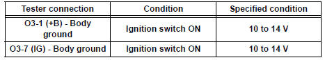
- Measure the voltage and resistance according to the value(s) in the table below.
Standard voltage
- Turn the ignition switch to the LOCK position.
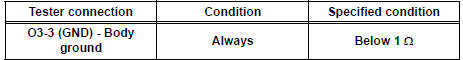
- Measure the resistance and resistance according to the value(s) in the table below.
Standard resistance
4 CHECK DTC
- Turn the ignition switch to the ON position.
(b) Clear the DTCs stored in memory (35).
HINT: First clear DTCs stored in the occupant classification ECU and then in the center airbag sensor assembly.
- Turn the ignition switch to the LOCK position.
- Turn the ignition switch to the ON position, and wait for at least 10 seconds.
- Using the intelligent tester, check the DTCs of the occupant classification ECU (35).
OK: DTC B1794 is not output. HINT: Codes other than code B1794 may be output at this time, but they are not related to this check.
USE SIMULATION METHOD TO CHECK
5 REPLACE OCCUPANT CLASSIFICATION ECU
- Turn the ignition switch to the LOCK position.
- Disconnect the negative (-) terminal cable from the battery, and wait for at least 90 seconds.
- Replace the occupant classification ECU
6 PERFORM ZERO POINT CALIBRATION
- Connect the negative (-) terminal cable to the battery.
- Connect the intelligent tester to the DLC3.
- Turn the ignition switch to the ON position.
- Using the intelligent tester, perform the "Zero point calibration" (28).
OK: The "COMPLETED" is displayed.
7 PERFORM SENSITIVITY CHECK
- Using the intelligent tester, perform the "Sensitivity check"
Standard value: 27 to 33 kg (59.52 to 72.75 lb)
END
 Occupant Classification Sensor Power Supply
Circuit Malfunction
Occupant Classification Sensor Power Supply
Circuit Malfunction
DTC B1793 Occupant Classification Sensor Power Supply
Circuit Malfunction
DESCRIPTION
The occupant classification sensor power supply circuit consists of the
occupant classification ECU and
the ...
 Occupant Classification ECU Malfunction
DTC B1795 Occupant Classification ECU Malfunction
DESCRIPTION
DTC B1795 is recorded when a malfunction is detected in the occupant
classification ECU.
Troubleshoot DTC B1771 first when the DTCs ...
Other materials:
Problem symptoms table
HINT:
If a normal code is displayed during the diagnostic trouble
code check although the trouble still occurs, check the
electrical circuits for each symptom in the order given in
the charts on the following pages and proceed to the page
given for troubleshooting.
The Matrix Chart is ...
Check mode procedure
1. CHECK MODE (SIGNAL CHECK): DTC CHECK
Connect the intelligent tester to the DLC3.
Turn the ignition switch to the ON position.
Select the "SIGNAL CHECK", and proceed
checking using the intelligent tester.
NOTICE:
Select the "SIGNAL CHECK" from the ...
Locking and unlocking the back door
Entry function (vehicles with a smart key system)
Carry the electronic key to enable this function.
Press the unlock button to
unlock all the doors.
The door cannot be unlocked for
3 seconds after the door is
locked.
Lock the back door again when
you leave the vehicle. The back
...
