Toyota Sienna Service Manual: Problem symptoms table
HINT:
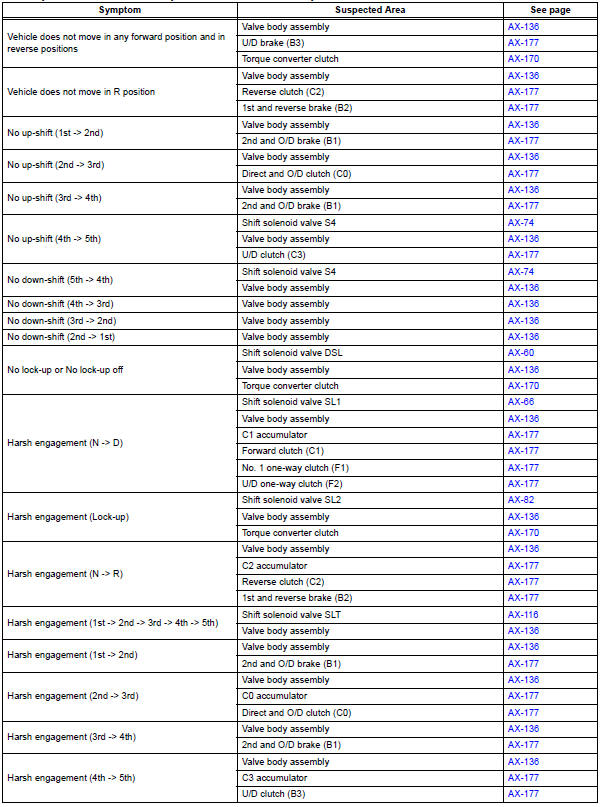
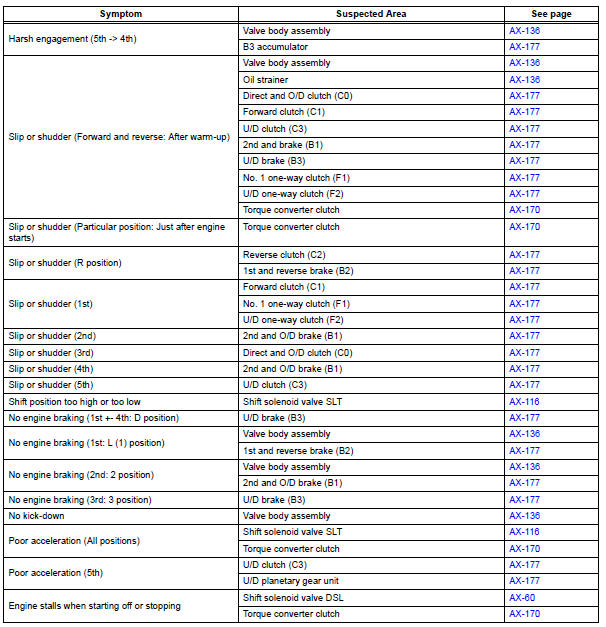
- If a normal code is displayed during the diagnostic trouble code check although the trouble still occurs, check the electrical circuits for each symptom in the order given in the charts on the following pages and proceed to the page given for troubleshooting.
- The Matrix Chart is divided into 2 chapters.
- When the circuit on which mark *1 is attached is a malfunction, DTC could be output.
Refer to the table below when the trouble cause is considered to be electrical. If the instruction PROCEED TO NEXT CIRCUIT INSPECTION SHOWN IN PROBLEM SYMPTOMS TABLE is given in the flowchart of each circuit, inspect the suspected areas in descending order for each symptom. If the trouble still occurs even though there are no abnormalities in the inspections listed for the symptoms, check and replace the ECM.
1. Chapter 1: Electronic Circuit Matrix Chart

2. Chapter 2: On-Vehicle Repair and Off-Vehicle Repair
 Monitor drive pattern
1. MONITOR DRIVE PATTERN FOR ECT TEST
(a) Perform this drive pattern as one method to
simulate the detection conditions of the ECT
malfunctions. (The DTCs may not be detected due
the actual drivin ...
 Terminals of ecm
1. Ecm
Hint:
each ecm terminal's standard voltage is shown in the
table below.
In the table, first follow the information under "condition".
Look under "symbols (terminal no. ...
Other materials:
Erasing the entire HomeLink® memory (all three programs)
Press and hold down the 2 outside
buttons for 10 seconds until
the indicator light flashes.
If you sell your vehicle, be sure to
erase the programs stored in the
HomeLink® memory.
Before programming
Install a new battery in the transmitter.
The battery side of the transmitter must ...
Diagnostic trouble code chart
If a trouble code is displayed during the DTC check, check
the circuit listed for that code. For details of each code, turn
the page mentioned below the "DTC No" in the DTC chart.
the "DTC No" in the DTC chart.
1. TRANSPONDER KEY ECU DIAGNOSTIC TROUBLE
CODE CHART
TRANSPON ...
System description
1. POWER MIRROR CONTROL SYSTEM DESCRIPTION
This system has these functions: automatic glare-resistant
electrochromic (EC) mirror, electrical remote control type
mirror, memory function, foot light function, and rear
window defogger-linked mirror defogger.
2. FUNCTION OF MAIN COMPONENT
...
