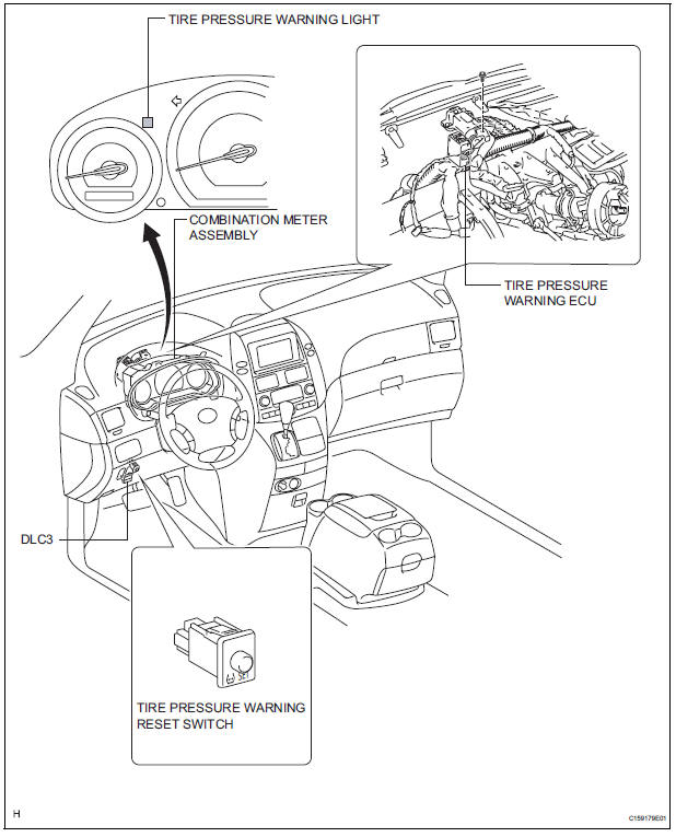
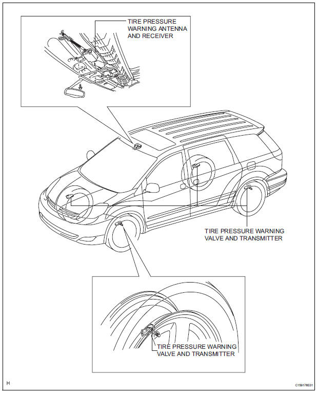
Toyota Sienna Service Manual: Parts location
SYSTEM DIAGRAM
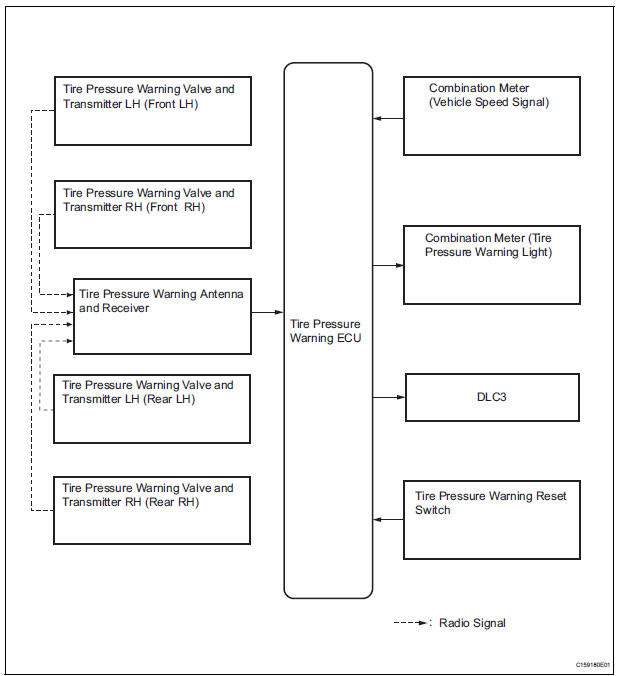
HINT: The tire pressure warning valve and transmitter sends information on the temperature inside the tire, the ID, and the tire pressure.
 Precaution
1. TIRE PRESSURE WARNING SYSTEM PRECAUTION
(a) When the tire pressure warning light comes on,
immediately check the tire pressure of the tire and
adjust it to the specified value. (The tire pre ...
 System description
1. DESCRIPTION OF SYSTEM
(a) A tire pressure warning valve and transmitter is
equipped with a tire pressure sensor and a
transmitter and is installed in a tire wheel assembly.
The sensor measure ...
Other materials:
Installing child restraints
Follow the child restraint system manufacturer’s instructions.
Firmly secure child restraints to the rear seats using the LATCH
anchors or a seat belt. Attach the top tether strap when installing
a child restraint.
The lap/shoulder belt can be used if your child restraint sy ...
Heated steering
wheel/seat heaters
Heated steering wheel and seat heaters heat the side grips of the
steering wheel and seats, respectively.
WARNING
Care should be taken to prevent injury if anyone in the
following categories
comes in contact with the steering wheel and seats when the heater
is on:
...
Shift Solenoid "D" Control Circuit
DESCRIPTION
Shifting from 1st to 5th is performed in combination with "ON" and "OFF"
operation of the shift solenoid
valves SL1, SL2, SL3, S4 and SR which are controlled by the ECM. If an open or
short circuit occurs in
either of the shift solenoid valves, the ECM cont ...
