Toyota Sienna Service Manual: Speed Signal Circuit
DESCRIPTION
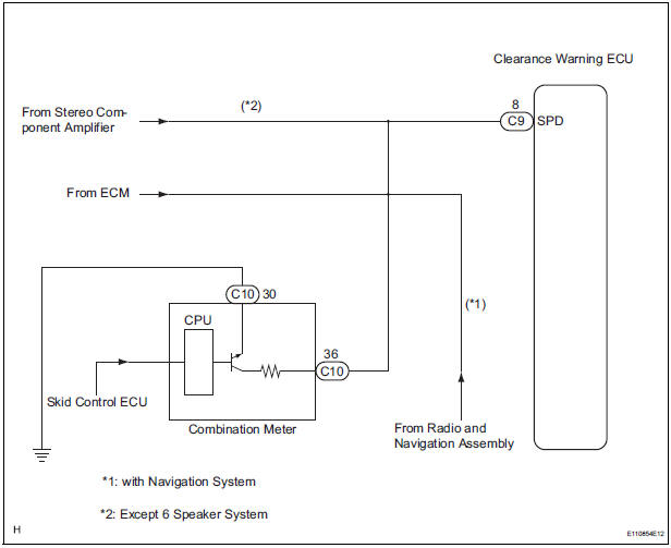
The clearance warning ECU receives the vehicle speed signal from the combination meter.
HINT:
- A voltage of 12 V or 5 V is output from each ECU and then input to the combination meter. The signal is changed to a pulse signal at the transistor in the combination meter. Each ECU controls the respective system based on the pulse signal.
- If a short occurs in an ECU, all systems in the diagram below will not operate normally.
WIRING DIAGRAM
INSPECTION PROCEDURE
1 CHECK OPERATION OF SPEEDOMETER
- Drive the vehicle and check if the function of the speedometer in the combination meter is normal.
OK: Actual vehicle speed and the speed indicated on the speedometer are the same.
HINT: The vehicle speed signal is normal when the indication on the speedometer is normal.
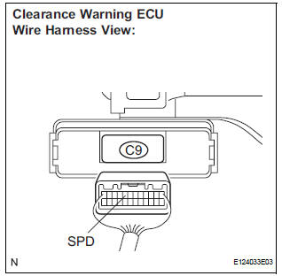
2 INSPECT CLEARANCE WARNING ECU
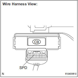
- Disconnect the clearance warning ECU connector C9.
- Measure the voltage.
- Jack up either one of the drive wheels.
- Move the shift lever to the neutral position.
- Turn the ignition switch to the ON position
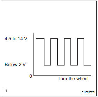
- Measure the voltage between terminal SPD of the clearance warning ECU and body ground when a drive wheel is turned slowly.
OK: Voltage pulses as shown.
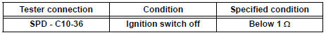
3 CHECK HARNESS AND CONNECTOR (COMBINATION METER - CLEARANCE WARNING ECU)
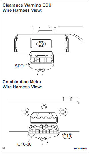
- Disconnect the combination meter C10 connector.
- Measure the resistance according to the value(s) in the table below.
Standard resistance
4 CHECK HARNESS AND CONNECTOR (COMBINATION METER AND EACH ECU - BODY GROUND)
- Measure the resistance according to the value(s) in the table below.
Standard resistance
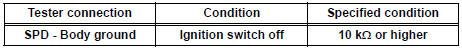
HINT: If the resistance between terminal SPD and body ground is less than 10 kΩ, there may be a short in a wire harness, connector, or ECU.
REPLACE COMBINATION METER
 Park / Neutral Position Switch Circuit
DESCRIPTION
The clearance warning ECU receives the reverse or park position signal from
the park / neutral position
switch.
WIRING DIAGRAM
INSPECTION PROCEDURE
1 INSPECT CLEARANCE WARNING E ...
 Back Sonar Sensor LH Circuit
DESCRIPTION
An ultrasonic sensor consists of a sensor portion that transmits and receives
ultrasonic waves and a preamplifier
that amplifies them. The ultrasonic sensor outputs the ultrasonic wave ...
Other materials:
Parts location
HOW TO PROCEED WITH
TROUBLESHOOTING
1 VEHICLE BROUGHT TO WORKSHOP
2 CUSTOMER PROBLEM ANALYSIS
(a) Confirm problem symptoms.
3 CHECK AND CLEAR DTCS
4 PROBLEM SYMPTOM CONFIRMATION
5 SYMPTOM SIMULATION
6 DTC CHECK (OTHER THAN MULTIPLEX DTC)
7 DTC CHART
8 PROBLEM SYMP ...
Disposal
1. DISPOSE OF SHOCK ABSORBER ASSEMBLY FRONT LH
HINT:
Dispose the RH side by the same procedures as the LH
side.
(a) Fully extend the shock absorber rod.
(b) Using a drill, make a hole in the cylinder as shown in
the illustration to discharge the gas inside.
CAUTION:
When dril ...
Inspection
1. INSPECT TIRE PRESSURE WARNING RESET SWITCH
(a) Remove the tire pressure warning reset switch.
(b) Measure the resistance between terminals 1 and 2
of the tire pressure warning reset switch when the
tire pressure warning switch is ON and OFF.
Standard resistance
If the result is not as ...
