Toyota Sienna Service Manual: Parts location
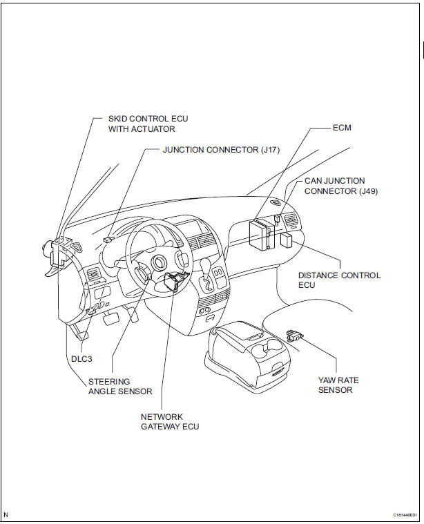
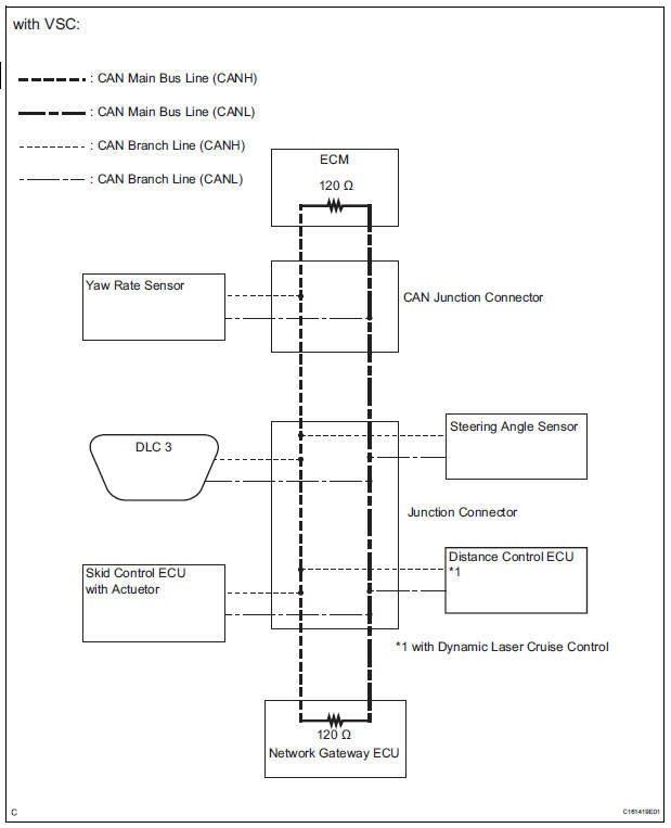
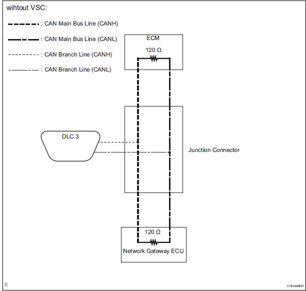
SYSTEM DIAGRAM
 Precaution
1. SRS AIRBAG SYSTEM HANDLING PRECAUTIONS
This vehicle is equipped with an SRS
(Supplemental Restraint System) such as the driver
airbag and front passenger airbag. Failure to carry
out serv ...
 System description
1. BRIEF DESCRIPTION
The CAN (Controller Area Network) is a serial data
communication system for real time application. It is
a vehicle multiplex communication system which
has a high commun ...
Other materials:
On-vehicle inspection
1. INSPECT CAMSHAFT TIMING CONTROL VALVE ASSEMBLY
Connect the intelligent tester to the DLC3.
Turn the ignition switch to the ON position.
Start the engine and warm it up.
Select the intelligent tester from the ACTIVE TEST
menu.
Check the engine speed ...
Open in Side Squib RH Circuit
DTC B0111/44 Open in Side Squib RH Circuit
DESCRIPTION
The side squib RH circuit consists of the center airbag sensor assembly and
the front seat side airbag
assembly RH.
The circuit instructs the SRS to deploy when deployment conditions are met.
DTC B0111/44 is recorded when an open circ ...
Registration Complete Indication Error/ Registration Demand Transmission/
Multiple Frame Incomplete
DTC 01-E0 Registration Complete Indication Error
DTC 01-E3 Registration Demand Transmission
DTC 01-E4 Multiple Frame Incomplete
DESCRIPTION
DTC No.
DTC Detection Condition
Trouble Area
01-E0
"Registration complete" signal from the master device
c ...
