Toyota Sienna Service Manual: Skid Control ECU Communication Stop Mode
DESCRIPTION
|
Detection Item |
Symptom |
Trouble Area |
| Skid Control ECU Communication Stop Mode |
|
|
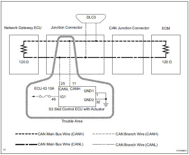
WIRING DIAGRAM
INSPECTION PROCEDURE
NOTICE:
- Turn the ignition switch off before measuring the resistances of CAN bus main wires and CAN bus branch wires.
- After the ignition switch is turned off, check that the key reminder warning system and light reminder warning system are not in operation.
- Before measuring the resistance, leave the vehicle as is for at least 1 minute and do not operate the ignition switch, any other switches, or the doors. If any doors need to be opened in order to check connectors, open the doors and leave them open.
HINT: Operating the ignition switch, any switches, or any doors triggers related ECU and sensor communication with the CAN. This communication will cause the resistance value to change.
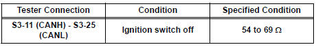
1 CHECK OPEN IN CAN BUS WIRE (SKID CONTROL ECU BRANCH WIRE)
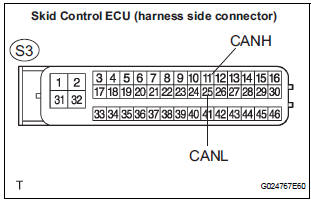
- Turn the ignition switch off.
- Disconnect the skid control ECU with Actuator connector.
- Measure the resistance according to the value(s) in the table below.
Standard resistance
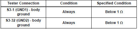
2 CHECK WIRE HARNESS (IG1, GND1, GND2)
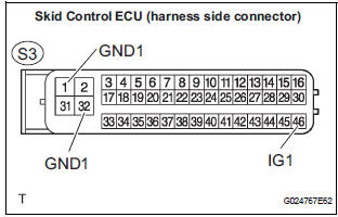
- Measure the resistance according to the value(s) in the table below.
Standard resistance
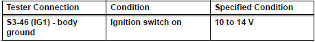
- Measure the voltage according to the value(s) in the table below.
Standard voltage
REPLACE ABS & TRACTION ACTUATOR ASSEMBLY
 Fail-safe chart
1. FAIL-SAFE FUNCTION
When communication fails in any of the main wires
(communication lines) due to a short circuit or other
causes, the fail-safe function, which is specified for
each syst ...
 Distance Control ECU Communication Stop Mode
DESCRIPTION
Detection Item
Symptom
Trouble Area
Distance Control ECU
Communication Stop
Mode
Distance control" is not displayed on the
&qu ...
Other materials:
Installation
1. REMOVE FRONT SEAT INNER BELT ASSEMBLY
HINT:
Refer to the instructions for reassembly of the front
seat assembly (for flat type).
Refer to the instructions for reassembly of the front
seat assembly (for manual seat).
Refer to the instructions for reassembly of the fr ...
Wrong Disc/ Disc cannot be Read
DTC 44-41 Wrong Disc
DTC 44-42 Disc cannot be Read
DESCRIPTION
DTC No.
DTC Detecting Condition
Trouble Area
44-41
An unsuitable disc is inserted
DVD
Television display assembly
44-42
The disc cannot be read.
IN ...
Reassembly
1. INSTALL NO. 1 SEAT CUSHION FRAME SUBASSEMBLY
LH
Install the seat cushion frame with the bolt.
Torque: Except 7-Passenger RH, M8 bolt
20.6 N*m (210 kgf*cm, 15 ft.*lbf)
M10 bolt
41 N*m (418 kgf*cm, 30 ft.*lbf)
2. INSTALL RECLINING CONTROL LINK SUBASSEMBLY
LH
Install ...
