Toyota Sienna Service Manual: Perform signal check
HINT:
- When entering signal check mode, the tire pressure
warning ECU sets all the signal check DTCs first.
After completing signal check for each inspection item, the DTCs for systems that are determined to be normal by the tire pressure warning ECU will be erased.
The DTCs for other inspection items may not be erased when only a certain signal is inspected.
- When signal check returns to normal mode, all the signal check DTCs will be erased.
(a) Make sure that the ignition switch is off.
(b) Connect the intelligent tester to DLC3.
(c) Turn the ignition switch to the ON position.
(d) Select the SIGNAL CHECK on the intelligent tester.
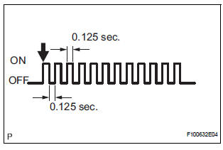
HINT: Every time the test mode DTC clear conditions are satisfied, the tire pressure warning light comes on for 1 second. Then, the tire pressure warning light blinks at 0.125-second intervals.
(e) Drive the vehicle at 12 mph (20 km/h) or more for 10 seconds or more to check the vehicle speed signal (C2191/91).
(f) Loosen the valve core and rapidly reduce the pressure (at least 40 kPa (0.41 kg/cm2, 5.8 psi) within 30 seconds or more) to check the transmitter data (C2181/81 to C2184/84).
HINT: The transmitter ID can be transmitted by rapidly reducing the tire pressure.
(g) Check that the tire pressure warning system test
mode DTCs are erased.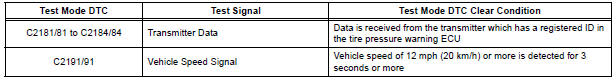
(h) Check the tire pressure warning reset switch.
(1) Press the tire pressure warning reset switch.
(2) Check the tire pressure warning indicator light.
(i) Result
HINT:
After the signal check is completed, check for a
signal check DTC to confirm the system status
(j) End of SIGNAL CHECK
After completing the test mode (SIGNAL CHECK), turn the ignition switch off and disconnect the tester.
DTC of SIGNAL CHECK (TEST DIAGNOSIS)
function:
If a trouble code is displayed during the test mode
DTC check, check the circuit listed for that code. For
details of each code, refer to the relevant page listed
under respective "DTC No." in the chart.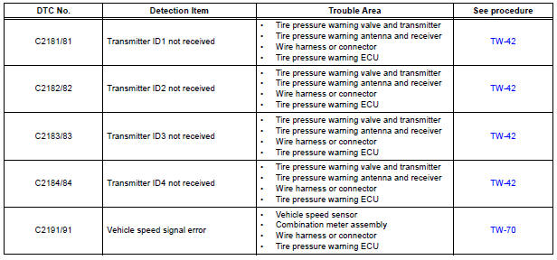
 Enter test mode
HINT:
Operation of the tire pressure warning reset switch
can be checked in TEST MODE.
During TEST MODE, the system is not initialized by
pushing the tire pressure warning reset switch. The
...
 Problem symptoms table
HINT:
Use the table below to help determine the cause of the
problem symptom. The potential causes of the symptoms
are listed in order of probability in the "Suspected Area"
column ...
Other materials:
Rear Clearance Sonar Sensor LH Circuit
DESCRIPTION
An ultrasonic sensor consists of a sensor portion that transmits and receives
ultrasonic waves and a preamplifier
that amplifies them. The ultrasonic sensor outputs the ultrasonic waves and
sends the received
signals to the clearance warning ECU.
WIRING DIAGRAM
INSPECTION PR ...
System diagram
1. DISC PLAYER OUTLINE
A CD player uses a laser pickup to read digital
signals recorded on CDs. By converting the digital
signals to analog, music and other content can be
played.
CAUTION:
Do not look directly at the laser pickup because
the CD player uses an invisible laser bea ...
Turning the high beam on/off manually
Switching to low beam
Pull the lever to the original
position.
Switching to high beam
Turn the light switch to the
position.
The Automatic High Beam can be operated when
The engine switch is in the “ON” position (vehicles without a smart key
system)
or IGNITION ON mode (vehicl ...
