Toyota Sienna Service Manual: Diagnosis system
1. BUS CHECK
- Select "BUS CHECK" from the "OBD/MOBD MENU" screen.
HINT: The ECUs and sensors that are properly connected to the CAN communication system can be displayed using the intelligent tester via the CAN VIM.
- Press "ENTER" on the intelligent tester.
- The screen displays the ECUs and sensors that are properly connected to the CAN communication system.
HINT: Properly connected ECUs or sensors that are not displayed on the screen indicate that a communication stop is occuring in the system, sensor, or ECU which is not displayed.
2. CHECK FOR INSTALLED SYSTEMS (ECUS AND SENSORS) THAT USE CAN COMMUNICATION
- Systems (ECUs, sensors) that use CAN communication vary depending on the vehicle's optional equipment. Check which systems (ECUs, sensors) are installed on the vehicle.
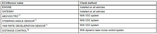
HINT:
- *1: with VSC
- *2: with Dynamic laser cruise control
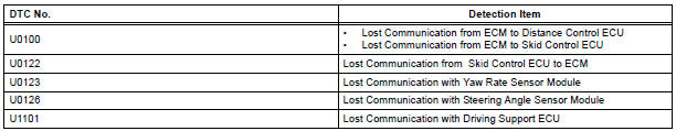
3. DTC TABLE BY ECU
HINT:
- For the CAN communication system, CAN communication system DTCs stored in certain ECUs can be displayed using the intelligent tester.
- If CAN communication system DTCs are output,
trouble cannot be determined only by the DTCs.
Perform troubleshooting according to "CHECK CAN BUS LINE" (See page CA-35).
- Skid control ECU (with VSC)
HINT: DTC communication uses the CAN communication system.

- ECM (with Dynamic laser cruise control)
HINT:
- DTC communication uses the CAN communication system.
- Distance control ECU data is output.
- Displayed on the "communication malfunction DTCs" screen of the intelligent tester. If U0235 or U1102 is output alone, the CAN communication is normal
- Gateway ECU
HINT: The network gateway ECU is connected to the CAN communication system, but CAN communication DTCs are not output.
4. DTCS COMBINATION TABLE
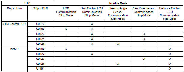
HINT: *1: with Dynamic laser cruise control
 Terminals of ECU
1. JUNCTION CONNECTOR
Junction connector
with VSC
HINT:
*1: with Dynamic laser cruise control
without VSC
CAN junction connector (with VSC)
with VSC
The connection ...
 Fail-safe chart
1. FAIL-SAFE FUNCTION
When communication fails in any of the main wires
(communication lines) due to a short circuit or other
causes, the fail-safe function, which is specified for
each syst ...
Other materials:
Removal
1. REMOVE WINDSHIELD WIPER MOTOR ASSEMBLY
2. REMOVE FRONT OUTER COWL TOP PANEL SUBASSEMBLY
3. DRAIN ENGINE COOLANT
4. REMOVE V-BANK COVER SUB-ASSEMBLY
5. REMOVE NO. 2 AIR CLEANER INLET
6. REMOVE NO. 1 AIR CLEANER INLET
7. REMOVE AIR CLEANER CAP SUB-ASSEMBLY
Disconnect the 3 vacuum hoses.
...
Driving the vehicle
The following procedures should be observed to ensure safe
driving:
Starting the engine
Driving
With the brake pedal depressed, shift the shift lever to D.
Release the parking brake.
Gradually release the brake pedal and gently depress the accelerator
pedal to accelerate the vehicle.
...
Installation
1. INSTALL BACK DOOR GLASS
Clean and shape the contact surface of the vehicle
body.
Using a knife, cut away any rough adhesive on
the contact surface of the body to ensure the
appropriate surface shape.
HINT:
Leave as much adhesive on the body as
possible.
& ...
