Toyota Sienna Service Manual: Problem symptoms table
ENTIRE SYSTEM
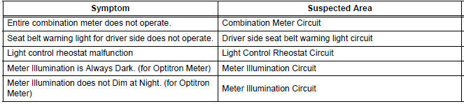
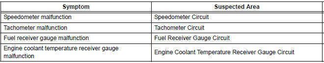
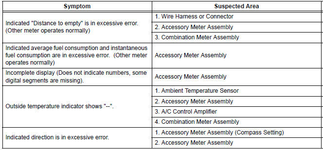
METER GAUGES
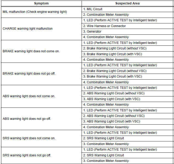
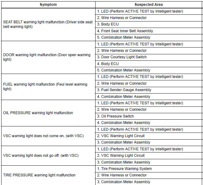
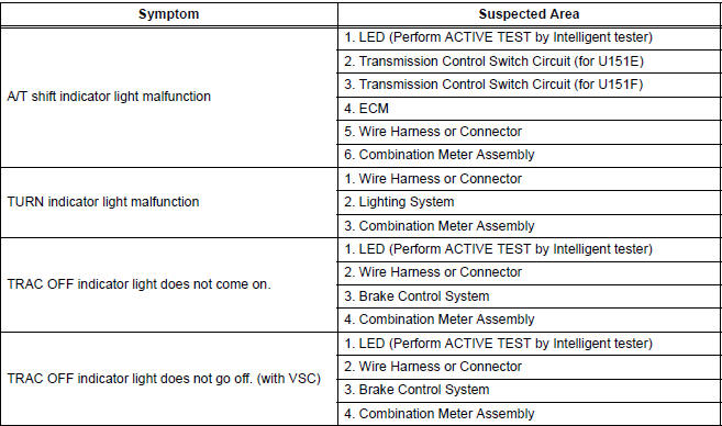
WARNING LIGHTS
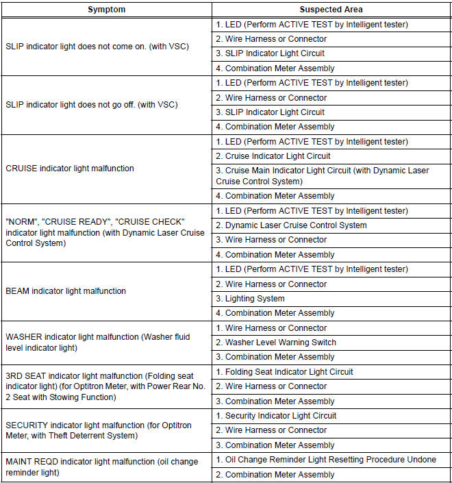
INDICATOR LIGHTS
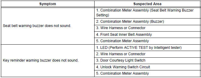
BUZZER
ACCESSORY METER ASSEMBLY
 Customize parameters
1. Seat Belt Buzzer ON/OFF Setting
The seat belt buzzer ON/OFF setting, which is a setting
of the buzzer function of the combination meter, can
disable the driver side seat belt buzzer and front
p ...
 Terminals of ECU
1. COMBINATION METER ASSEMBLY
*1: with Power Rear No. 2 Seat with Stowing Function
*2: with Theft Deterrent System
Waveform 1 (Reference) : Using an oscilloscope:
OK ...
Other materials:
Unmatched Key Code
DTC B2795 Unmatched Key Code
DESCRIPTION
This DTC is output when a key with a code that has not been registered in the
ECU is inserted into the
ignition key cylinder.
DTC No.
DTC Detection Condition
Trouble Area
B2795
Key with unregistered key code is i ...
Diagnostic trouble code chart
HINT:
If a malfunction code is displayed during the DTC check,
check the circuit indicated by the DTC. For details of each
code, turn to the page for the respective "DTC Code" in the
DTC chart.
DTC chart of ABS:
DTC chart of VSC:
...
Inspection
1. INSPECT FRONT SPEED SENSOR
(a) Make sure that there is no looseness at the
connector lock part and connecting part of the
connector.
(b) Disconnect the speed sensor connector.
(c) Measure the resistance between terminals 1 and 2
of the speed sensor connector.
OK:
Resistance:
0.92 ...
