Toyota Sienna Service Manual: Inspection
1. INSPECT FRONT SPEED SENSOR
(a) Make sure that there is no looseness at the connector lock part and connecting part of the connector.
(b) Disconnect the speed sensor connector.
(c) Measure the resistance between terminals 1 and 2 of the speed sensor connector.
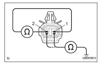
OK: Resistance: 0.92 to 1.22 kΩ
(d) Measure the resistance between terminals 1 and 2 of the speed sensor connector and body ground.
OK: Resistance: 1MΩ or higher
 Removal
HINT:
Remove the RH side by same procedures with LH side.
1. REMOVE FRONT WHEEL
2. REMOVE FRONT FENDER LINER LH
3. REMOVE FRONT SPEED SENSOR LH
(a) Disconnect the speed sensor connector.
( ...
 Installation
HINT:
Install the RH side by the same procedures with LH side.
1. INSTALL FRONT SPEED SENSOR LH
(a) Install the speed sensor front LH with the bolt.
Torque: 8.0 N*m (82 kgf*cm, 71 in.*lbf)
NO ...
Other materials:
ECM / PCM Processor
DTC P0606 ECM / PCM Processor
DESCRIPTION
The ECM continuously monitors its internal processors (CPUs), A/F sensor
transistors and heated oxygen
sensor (HO2S) transistors. This self-check ensures that the ECM is functioning
properly. These are
diagnosed by internal "mirroring" of t ...
Short to B+ in Curtain Shield Squib LH Circuit
DTC B1168/86 Short to B+ in Curtain Shield Squib LH Circuit
DESCRIPTION
The curtain shield squib LH circuit consists of the center airbag sensor
assembly and the curtain shield
airbag assembly LH.
The circuit instructs the SRS to deploy when deployment conditions are met.
DTC B1168/86 is ...
Removal
HINT:
Replace the RH side by the same procedures as the LH side.
1. REMOVE REAR WHEEL
2. REMOVE REAR AXLE SHAFT LH NUT (See page DS-
22)
3. SEPARATE REAR DISC BRAKE CALIPER
ASSEMBLY LH
(a) Removing the 2 bolts, separate the rear disc brake
caliper assembly LH.
4. REMOVE REAR DISC
5. SEPARA ...
