Toyota Sienna Service Manual: Rear blower resistor
ON-VEHICLE INSPECTION
1. INSPECT REAR BLOWER MOTOR CONTROLLER
(a) Measure resistance according to the value(s) in the table below..
Standard resistance 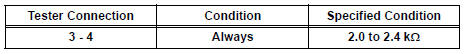
If the resistance is not as specified, replace the rear blower motor controller.
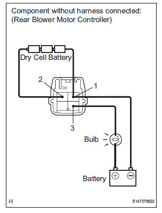
(b) Inspect the rear blower motor controller.
(1) Connect the positive (+) lead to terminal 3 through a 12 V to 3.4 W test bulb and negative (-) lead to terminal 1.
(2) Connect the three 1.5 V dry cell batteries' positive (+) lead to terminal 2, and the negative (-) lead to terminal 1. Then check that the test bulb comes on.
OK: The test bulb comes on.
If operation is not as specified, replace the rear blower motor controller.
 For rear air conditioning system
ON-VEHICLE INSPECTION
1. INSPECT REAR AIR MIX CONTROL SERVO MOTOR
(a) Inspect servo motor operation.
(1) Connect the positive (+) lead from the battery
to terminal 4 and negative (-) lead to ...
 Compressor and magnetic clutch
COMPONENTS
...
Other materials:
Oxygen Sensor Circuit
HINT:
Sensor 2 refers to the sensor mounted behind the Three-Way Catalytic
Converter (TWC) and located far
from the engine assembly.
DESCRIPTION
A three-way catalytic converter (TWC) is used in order to convert the carbon
monoxide (CO), hydro
carbon (HC), and nitrogen oxides (HOx) into ...
Removal
1. REMOVE BATTERY (See page EM-26)
2. REMOVE NO. 2 AIR CLEANER INLET (See page EM-
28)
3. REMOVE AIR CLEANER CAP SUB-ASSEMBLY (See
page FU-13)
4. REMOVE AIR CLEANER FILTER ELEMENT (See page
EM-28)
5. REMOVE AIR CLEANER CASE SUB-ASSEMBLY (See
page EM-28)
6. REMOVE AIR CLEANER BRACKET
(a ...
Seat Position Airbag Sensor Circuit Malfunction
DTC B1153/25 Seat Position Airbag Sensor Circuit Malfunction
DESCRIPTION
The seat position airbag sensor circuit consists of the center airbag sensor
assembly and the seat
position airbag sensor.
DTC B1153/25 is recorded when a malfunction is detected in the seat position
airbag sensor cir ...
