Toyota Sienna Service Manual: Removal
1. REMOVE BATTERY (See page EM-26) 2. REMOVE NO. 2 AIR CLEANER INLET (See page EM- 28) 3. REMOVE AIR CLEANER CAP SUB-ASSEMBLY (See page FU-13) 4. REMOVE AIR CLEANER FILTER ELEMENT (See page EM-28) 5. REMOVE AIR CLEANER CASE SUB-ASSEMBLY (See page EM-28) 6. REMOVE AIR CLEANER BRACKET
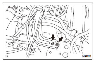
(a) Remove the 2 bolts and the air cleaner bracket.
7. REMOVE NO. 1 AIR CLEANER INLET
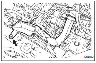
(a) Remove the bolt and the No. 1 air cleaner inlet.
8. REMOVE STARTER ASSEMBLY
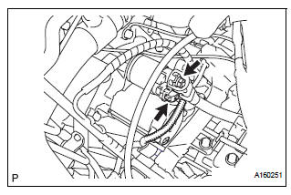
(a) Disconnect the starter connector.
(b) Open the terminal cap and remove the nut and the starter wire.
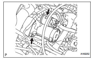
(c) Remove the 2 bolts and the starter.
 Starter
Components
...
 Disassembly
1. Remove repair service starter kit
(a) Remove the nut and disconnect the lead wire from
the repair service starter kit.
(b) Remove the 2 screws which are used to secure the
repair servic ...
Other materials:
Cranking Holding Function Circuit
DESCRIPTION
The system detects the ignition switch's starting signal (STSW) and then
supplies current to the starter
until the ECM judges that the engine has started successfully. The purpose is to
reduce the holding time
of the ignition key.
WIRING DIAGRAM
Refer to DTC P0617.
INSPECTI ...
Front Occupant Classification Sensor RH Circuit
Malfunction
DTC B1781 Front Occupant Classification Sensor RH Circuit
Malfunction
DESCRIPTION
The front occupant classification sensor RH circuit consists of the occupant
classification ECU and the
front occupant classification sensor RH.
DTC B1781 is recorded when a malfunction is detected in the fron ...
Installation
1. INSTALL FRONT DOOR WINDOW FRAME MOULDING
Remove the tape from the front door window frame
moulding.
Clean the contact surface of the vehicle body with
white gasoline.
Clean the outer circumference of the front door
window frame moulding with white gasoline.
Apply new double-si ...
