Toyota Sienna Service Manual: Rear Occupant Classification Sensor RH Circuit Malfunction
DTC B1783 Rear Occupant Classification Sensor RH Circuit Malfunction
DESCRIPTION
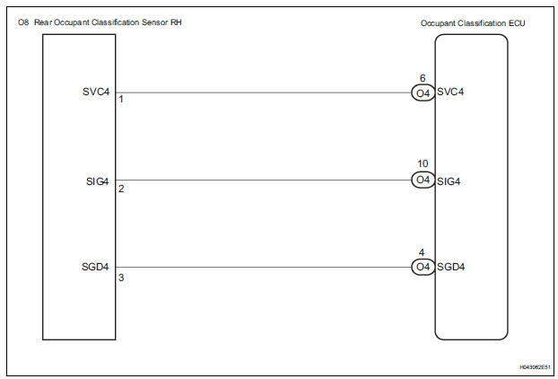
The rear occupant classification sensor RH circuit consists of the occupant classification ECU and the rear occupant classification sensor RH.
DTC B1783 is recorded when a malfunction is detected in the rear occupant classification sensor RH circuit
|
DTC No. |
DTC Detecting Condition |
Trouble Area |
|
B1783 |
|
|
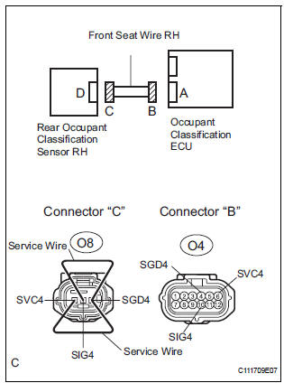
WIRING DIAGRAM
INSPECTION PROCEDURE
HINT:
- If troubleshooting (wire harness inspection) is difficult to perform, remove the front passenger seat installation bolts to see the under surface of the seat cushion.
- In the above case, hold the seat so that it does not fall down. Holding the seat for a long period of time may cause a problem, such as seat rail deformation. Hold the seat only as necessary.
1 CHECK DTC
- Turn the ignition switch to the ON position.
- Clear the DTCs stored in the memory.
HINT: First clear DTCs stored in the occupant classification ECU and then in the center airbag sensor assembly.
- Turn the ignition switch to the LOCK position.
- Turn the ignition switch to the ON position.
- Check the DTCs (35).
OK: DTC B1783 is not output. HINT: Codes other than DTC B1783 may be output at this time, but they are not related to this check.
 USE SIMULATION METHOD TO
CHECK
USE SIMULATION METHOD TO
CHECK

2 CHECK CONNECTION OF CONNECTORS
- Turn the ignition switch to the LOCK position.
- Disconnect the negative (-) terminal cable from the battery, and wait for at least 90 seconds.
- Check that the connectors are properly connected to the occupant classification ECU and the rear occupant classification sensor RH.
OK: The connectors are properly connected
 CONNECT CONNECTORS, THEN GO
TO
STEP 1
CONNECT CONNECTORS, THEN GO
TO
STEP 1

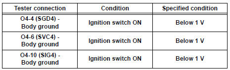
3 CHECK FRONT SEAT WIRE RH (SHORT TO B+)
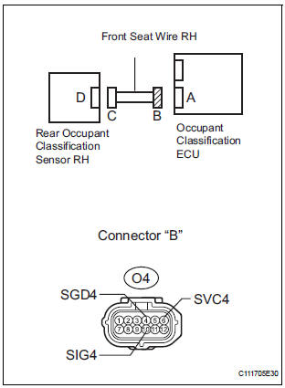
- Disconnect the connectors from the occupant classification ECU and the rear occupant classification sensor RH.
- Connect the negative (-) terminal cable to the battery.
- Turn the ignition switch to the ON position.
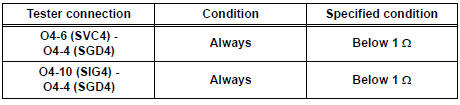
- Measure the voltage according to the value(s) in the table below.
Standard voltage

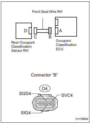
4 CHECK FRONT SEAT WIRE RH (OPEN)
- Turn the ignition switch to the LOCK position.
- Disconnect the negative (-) terminal cable from the battery, and wait for at least 90 seconds.
- Using a service wire, connect O8-1 (SVC4) and O8-3
(SGD4), and connect O8-2 (SIG4) and O8-3 (SGD4) of
connector "C".
NOTICE: Do not forcibly insert a service wire into the terminals of the connector when connecting.
- Measure the resistance according to the value(s) in the table below.
Standard resistance

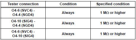
5 CHECK FRONT SEAT WIRE RH (SHORT)
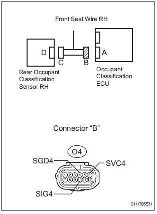
- Disconnect the service wire from connector "C".
- Measure the resistance according to the value(s) in the table below.
Standard resistance

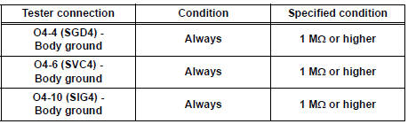
6 CHECK FRONT SEAT WIRE RH (SHORT TO GROUND)
- Measure the resistance according to the value(s) in the table below.
Standard resistance

7 CHECK DTC
- Connect the connectors to the occupant classification ECU and the rear occupant classification sensor RH.
- Connect the negative (-) terminal cable to the battery.
- Turn the ignition switch to the ON position.
- Clear the DTCs stored in the memory.
HINT: First clear DTCs stored in the occupant classification ECU and then in the center airbag sensor assembly.
- Turn the ignition switch to the LOCK position.
- Turn the ignition switch to the ON position.
- Check the DTCs (35).
OK: DTC B1783 is not output. HINT: Codes other than DTC B1783 may be output at this time, but they are not related to this check.

8 REPLACE OCCUPANT CLASSIFICATION ECU
- Turn the ignition switch to the LOCK position.
- Disconnect the negative (-) terminal cable from the battery, and wait for at least 90 seconds.
- Replace the occupant classification ECU.
HINT: Perform the inspection using parts from a normal vehicle if possible.

9 PERFORM ZERO POINT CALIBRATION
- Connect the negative (-) terminal cable to the battery.
- Connect the intelligent tester to the DLC3.
- Turn the ignition switch to the ON position.
- Using the intelligent tester, perform "Zero point calibration" (28).
OK: "COMPLETED" is displayed


10 PERFORM SENSITIVITY CHECK
- Using the intelligent tester, perform "Sensitivity check" (28).
Standard value: 27 to 33 kg (59.52 to 72.75 lb)


11 CHECK DTC
- Connect the negative (-) terminal cable to the battery.
- Turn the ignition switch to the ON position.
- Clear the DTCs stored in the memory.
HINT: First clear DTCs stored in the occupant classification ECU and then in the center airbag sensor assembly.
- Turn the ignition switch to the LOCK position.
- Turn the ignition switch to the ON position.
- Check the DTCs (35).
OK: DTC B1783 is not output. HINT: Codes other than DTC B1783 may be output at this time, but they are not related to this check.

12 REPLACE FRONT SEAT ASSEMBLY RH
- Turn the ignition switch to the LOCK position.
- Disconnect the negative (-) terminal cable from the battery, and wait for at least 90 seconds.
- Replace the front seat assembly RH ( for flat type, SE-48 for manual seat, SE-58 for power seat).

13 PERFORM ZERO POINT CALIBRATION
- Connect the negative (-) terminal cable to the battery.
- Connect the intelligent tester to the DLC3.
- Turn the ignition switch to the ON position.
- Using the intelligent tester, perform "Zero point calibration"
OK: "COMPLETED" is displayed
14 PERFORM SENSITIVITY CHECK
- Using the intelligent tester, perform "Sensitivity check" (28).
Standard value: 27 to 33 kg (59.52 to 72.75 lb)
END
 Rear Occupant Classification Sensor LH Circuit
Malfunction
Rear Occupant Classification Sensor LH Circuit
Malfunction
DTC B1782 Rear Occupant Classification Sensor LH Circuit
Malfunction
DESCRIPTION
The rear occupant classification sensor LH circuit consists of the occupant
classification ECU and the rear
occup ...
 Front Occupant Classification Sensor LH Collision
Detection
Front Occupant Classification Sensor LH Collision
Detection
DTC B1785 Front Occupant Classification Sensor LH Collision
Detection
DESCRIPTION
DTC B1785 is output when the occupant classification ECU receives a collision
detection signal sent by
the front ...
Other materials:
Using the AUX port
To use the AUX port, connect a portable player, press the
“AUDIO” button, then select “AUX” to display the audio control
screen.
Connecting a portable audio player
Operating portable audio players connected to the audio system
The volume can be adjusted using the vehicle’s audio contr ...
ACC Power Source Circuit
DESCRIPTION
This circuit supplies power to the A/C amplifier and the illumination for the
clock.
WIRING DIAGRAM
INSPECTION PROCEDURE
1 INSPECT FUSE (ECU ACC)
(a) Remove the ECU ACC fuse from the engine room relay
block.
(b) Measure the resistance according to the value(s) in the
tab ...
Disassembly
1. INSPECT UNDERDRIVE PLANETARY GEAR
PRELOAD
HINT:
(See page AX-260)
2. REMOVE FRONT PLANETARY GEAR NUT
(a) Using SST, loosen the staked part of the lock nut.
SST 09930-00010 (09931-00010, 09931-00020),
09387-00050
(b) Place the underdrive planetary gear in a soft jaw
vise.
NOTIC ...
