Toyota Sienna Service Manual: Disassembly
1. INSPECT UNDERDRIVE PLANETARY GEAR PRELOAD
HINT: (See page AX-260)
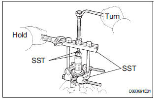
2. REMOVE FRONT PLANETARY GEAR NUT
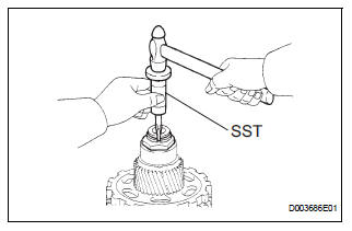
(a) Using SST, loosen the staked part of the lock nut.
SST 09930-00010 (09931-00010, 09931-00020), 09387-00050
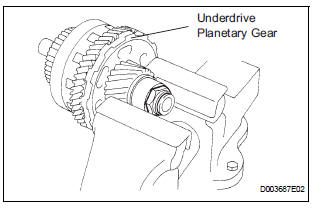
(b) Place the underdrive planetary gear in a soft jaw vise.
NOTICE: Be careful not to damage the differential drive pinion.
(c) Using a socket wrench, remove the lock nut.
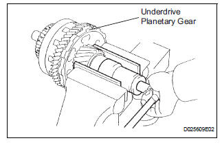
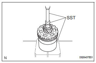
3. REMOVE CYLINDRICAL ROLLER BEARING RACE INNER
(a) Using SST, remove the cylindrical roller bearing race inner.
SST 09950-00020, 09950-00030, 09950-60010 (09951-00320, 09957-04010)
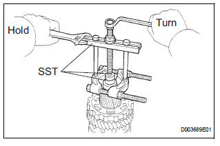
4. REMOVE UNDERDRIVE PLANETARY GEAR ASSEMBLY
(a) Using SST and a press, remove the differential drive pinion, parking lock gear, counter driven gear with underdrive planetary ring gear and radial ball bearing front.
SST 09950-60010 (09951-00320), 09387-00050, 09950-00020, 09950-00030, 09950-40011 (09957-04010)
(b) Place the underdrive planetary gear in a soft jaw vise.
(c) Using SST, remove the radial ball bearing rear from the underdrive planetary gear
SST 09950-60010 (09951-00320), 09950-00030, 09950-40011 (09957-04010)
5. REMOVE UNDERDRIVE PLANETARY RING GEAR
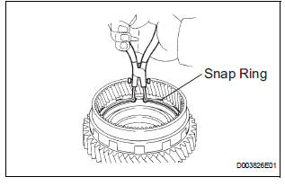
(a) Using a snap ring pliers, remove the snap ring.
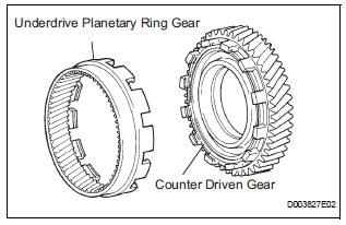
(b) Remove the underdrive planetary ring gear from the counter driven gear.
 Underdrive planetary gear
COMPONENTS
...
 Inspection
1. INSPECT UNDERDRIVE PLANETARY GEAR PRELOAD
(a) Using SST, fix the underdrive planetary gear
assembly.
SST 09387-00050
(b) Using SST and a torque wrench, measure the
turning torque of th ...
Other materials:
Programming the HomeLink® (for U.S.A. owners)
The HomeLink® compatible transceiver in your vehicle has 3 buttons
which can be programmed to operate 3 different devices. Refer to the
programming method below appropriate for the device.
Indicator light
Buttons
Programming the HomeLink®
Point the remote control for
the d ...
Opening/closing the sliding door
Sliding door handle
Open/close
Vehicles with power sliding
doors: The sliding door will be
automatically and completely
opened and closed by the following.
Pulling the outside handle.
Sliding the inside handle forward
to close or backward to
open.
Power sliding door switches (v ...
EVAP System
RELATED DTCS
If any EVAP system DTCs are set, the malfunctioning area can be determined
using the table below.
NOTICE:
If the 0.02 inch reference pressure difference between the first and second
checks is greater than
the specification, the DTCs corresponding to the reference pressur ...
