Toyota Sienna Service Manual: ACC Power Source Circuit
DESCRIPTION
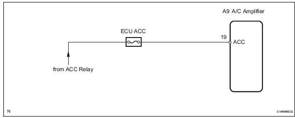
This circuit supplies power to the A/C amplifier and the illumination for the clock.
WIRING DIAGRAM
INSPECTION PROCEDURE
1 INSPECT FUSE (ECU ACC)
(a) Remove the ECU ACC fuse from the engine room relay block.
(b) Measure the resistance according to the value(s) in the table below.
Standard resistance 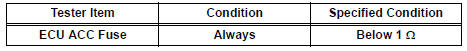
2 CHECK HARNESS AND CONNECTOR (A/C AMPLIFIER - BATTERY)
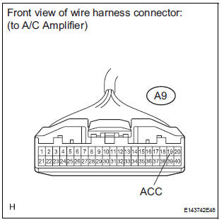
(a) Disconnect the connector from the A/C amplifier.
(b) Measure the voltage according to the value(s) in the table below.
Standard voltage 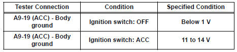

PROCEED TO NEXT CIRCUIT INSPECTION SHOWN IN PROBLEM SYMPTOMS TABLE
 IG Power Source Circuit
DESCRIPTION
The main power source is supplied to the A/C amplifier when the ignition
switch is turned to the ON
position.
The power source is used for operating the A/C amplifier and servo moto ...
 Back-up Power Source Circuit
DESCRIPTION
This is the back-up power source for the A/C amplifier. Power is supplied
even when the ignition switch is
off and is used for diagnostic trouble code memory, etc.
WIRING DIAGRAM
...
Other materials:
Short in Rear Curtain Shield Squib RH Circuit
DTC B1630/83 Short in Rear Curtain Shield Squib RH Circuit
DESCRIPTION
The rear curtain shield squib RH circuit consists of the center airbag sensor
assembly and the curtain
shield airbag assembly RH.
The circuit instructs the SRS to deploy when deployment conditions are met.
DTC B1630/83 ...
Installation
1. INSTALL AMPLIFIER ANTENNA ASSEMBLY
Engage the 16 clamps to install the amplifier
antenna assembly.
Install the 3 bolts.
Connect the connectors.
2. INSTALL ROOF HEADLINING ASSEMBLY
3. INSTALL ANTENNA ASSEMBLY WITH HOLDER
Install the antenna assembly ...
DRL Relay Circuit
DESCRIPTION
The Multiplex network body ECU controls the DRL No.2 relay
WIRING DIAGRAM
INSPECTION PROCEDURE
1 PERFORM ACTIVE TEST BY INTELLIGENT TESTER
Connect the intelligent tester to DLC3.
Turn the ignition switch ON and push the intelligent
tester main switch ON.
Sel ...
