Toyota Sienna Service Manual: Removal
1. DRAIN POWER STEERING FLUID
2. REMOVE FRONT WHEEL RH
3. REMOVE FRONT FENDER APRON SEAL RH (See page EM-26)
4. REMOVE FAN AND GENERATOR V BELT (See page EM-6)
5. DISCONNECT NO. 1 FLUID RESERVOIR TO PUMP HOSE
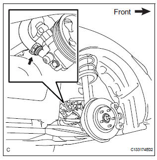
(a) Slide the clip and disconnect the No. 1 fluid reservoir to pump hose from the vane pump assembly.
6. DISCONNECT PRESSURE FEED TUBE ASSEMBLY
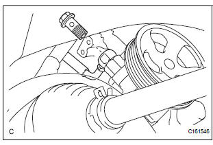
(a) Remove the union bolt and disconnect the pressure feed tube assembly from the vane pump assembly.
(b) Remove the gasket from the pressure feed tube assembly.
7. DISCONNECT POWER STEERING FLUID PRESSURE SWITCH CONNECTOR
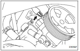
(a) Disconnect the power steering fluid pressure switch connector.
8. REMOVE VANE PUMP ASSEMBLY
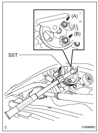
(a) Using SST, loosen bolt (A) and remove bolt (B), and then remove the vane pump assembly.
SST 09249-63010
(b) Remove the bolt from the vane pump assembly.
 Vane pump
COMPONENTS
...
 Disassembly
1. HOLD VANE PUMP ASSEMBLY
(a) Using SST, hold the vane pump assembly in a vise.
SST 09630-00014 (09631-00132)
2. REMOVE POWER STEERING SUCTION PORT UNION
(a) Remove the bolt and the pow ...
Other materials:
Initialization
1. RESET
When the control motor and clutch is replaced:
The power slide door ECU cannot receive a switch
signal from the control motor and clutch. This may
cause the power slide door system to enter fail-safe
mode and DTC (B2224 (LH) or B2223 (RH)) to set,
and also make the syste ...
Basic inspection
(a) WHEN MEASURING RESISTANCE OF
ELECTRONIC PARTS
(1) Unless otherwise stated, all resistance
measurements should be made at an ambient
temperature of 20°C (68°F). Resistance
measurements may be inaccurate if measured
at high temperatures, i.e. immediately after the
vehicle has been running ...
DSP Error
DTC 44-78 DSP Error
DESCRIPTION
DTC No.
DTC Detection Condition
Trouble Area
44-78
An error occurs during the decode process (MP3 /
WMA).
-
INSPECTION PROCEDURE
HINT:
After the inspection is completed, clear the DTCs.
NOTICE:
Th ...
