Toyota Sienna Service Manual: Disassembly
1. HOLD VANE PUMP ASSEMBLY
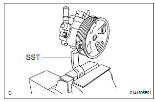
(a) Using SST, hold the vane pump assembly in a vise.
SST 09630-00014 (09631-00132)
2. REMOVE POWER STEERING SUCTION PORT UNION
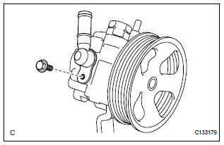
(a) Remove the bolt and the power steering suction port union from the vane pump front housing.
(b) Using a screwdriver, remove the O-ring from the power steering suction port union.
3. REMOVE POWER STEERING FLUID PRESSURE SWITCH
NOTICE: Perform this procedure only when the power steering fluid pressure switch is replaced.
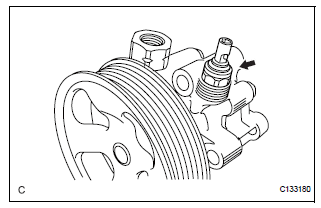
(a) Remove the power steering fluid pressure switch from the vane pump front housing.
4. REMOVE FLOW CONTROL VALVE ASSEMBLY
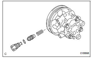
(a) Remove the pressure port union from the vane pump front housing.
(b) Remove the O-ring from the pressure port union.
(c) Remove the flow control valve assembly and the flow control valve compression spring from the vane pump front housing.
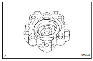
5. REMOVE VANE PUMP REAR HOUSING
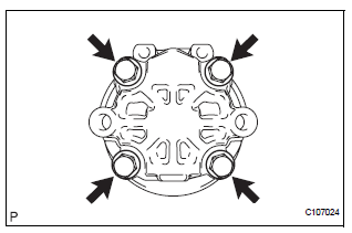
(a) Remove the 4 bolts and vane pump rear housing from the vane pump front housing.
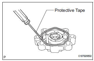
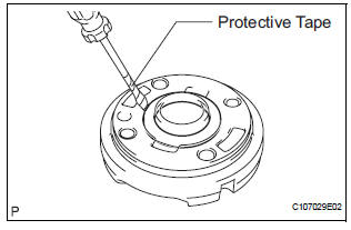
(b) Using a screwdriver, remove the O-ring from the vane pump rear housing.
HINT: Tape the screwdriver tip before use.
6. REMOVE VANE PUMP SHAFT WITH PULLEY
(a) Using 2 screwdrivers, remove the vane pump shaft snap ring from the vane pump shaft with pulley.
(b) Remove the vane pump shaft with pulley.
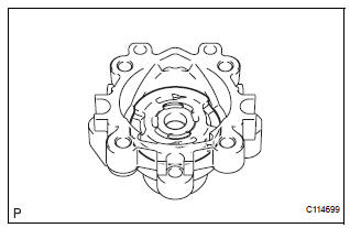
7. REMOVE VANE PUMP ROTOR
(a) Remove the 10 vane pump plates.
(b) Remove the vane pump rotor.
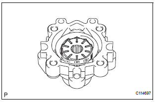
8. REMOVE VANE PUMP CAM RING
(a) Remove the vane pump cam ring from the vane pump front housing.
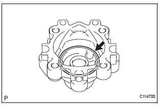
9. REMOVE VANE PUMP FRONT SIDE PLATE
(a) Remove the vane pump front side plate from the vane pump front housing.
(b) Using a screwdriver, remove the O-ring from the vane pump front side plate.
HINT: Tape the screwdriver tip before use.
(c) Remove the O-ring from the vane pump front housing.
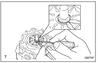
10. REMOVE VANE PUMP HOUSING OIL SEAL
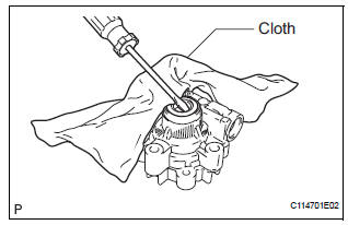
(a) Using a screwdriver and a shop rag or a piece of cloth, remove the vane pump housing oil seal from the vane pump front housing.
NOTICE: Be careful not to damage the vane pump front housing.
 Removal
1. DRAIN POWER STEERING FLUID
2. REMOVE FRONT WHEEL RH
3. REMOVE FRONT FENDER APRON SEAL RH (See
page EM-26)
4. REMOVE FAN AND GENERATOR V BELT (See page
EM-6)
5. DISCONNECT NO. 1 FLUID RESERVOI ...
 Inspection
1. INSPECT VANE PUMP SHAFT AND BUSHING IN VANE PUMP FRONT HOUSING
(a) Using a micrometer, measure the outer diameter [a]
of the vane pump shaft with pulley.
(b) Using vernier calipers, measur ...
Other materials:
Roof luggage carrier (if equipped)
Roof luggage carrier components
Roof rails
Cross rails
Adjusting the position of cross rails
Turn the knobs counterclockwise
to release the cross
rails.
Slide the cross rails to the
appropriate position for loading
luggage and turn the
knobs clockwise to tigh ...
Engine coolant temperature sensor
COMPONENTS
REMOVAL
1. DRAIN ENGINE COOLANT (See page CO-6)
2. REMOVE V-BANK COVER SUB-ASSEMBLY (See
page EM-28)
3. REMOVE NO. 2 AIR CLEANER INLET (See page EM-
28)
4. REMOVE NO. 1 AIR CLEANER INLET (See page EM-
28)
5. REMOVE AIR CLEANER CAP SUB-ASSEMBLY (See
page ES-493)
6. REMOVE AI ...
Removal
HINT:
Replace the RH side by the same procedures as the LH side.
1. REMOVE REAR WHEEL
2. REMOVE REAR AXLE SHAFT LH NUT (See page DS-
22)
3. SEPARATE REAR DISC BRAKE CALIPER
ASSEMBLY LH
(a) Removing the 2 bolts, separate the rear disc brake
caliper assembly LH.
4. REMOVE REAR DISC
5. SEPARA ...
