Toyota Sienna Service Manual: Removal
1. REMOVE REAR DOOR SCUFF PLATE
2. REMOVE REAR DOOR WEATHERSTRIP
3. REMOVE BACK DOOR WEATHERSTRIP
4. REMOVE BACK DOOR SCUFF PLATE
5. REMOVE FRONT QUARTER TRIM PANEL ASSEMBLY
- Remove the floor anchor cover.
- Remove the bolt and disconnect the No. 2 rear seat outer belt assembly on the floor anchor side.
- Remove the 2 package holder net hooks.
- Using a screwdriver, disengage the claw and remove the courtesy light.
- Disconnect the courtesy light connectors.
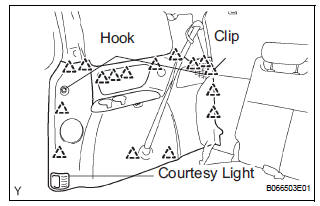
- Using a screwdriver, disengage the 16 clips and remove the quarter trim panel assembly.
HINT: Tape the screwdriver tip before use.
6. REMOVE REAR WINDOW SIDE GARNISH ASSEMBLY
7. REMOVE NO. 1 REAR SEAT OUTER BELT ASSEMBLY (for 7-Passenger)
HINT: Refer to the instructions for disassembly of the rear No. 1 seat assembly (for captain seat type).
- Remove the rear seatback board RH.
- Remove the rear seat shoulder belt cover.
- Remove the bolt, nut and No. 1 rear seat outer belt assembly.
8. REMOVE 3 POINT TYPE REAR SEAT BELT ASSEMBLY (for 8-Passenger)
- Remove the nut and disconnect the 3 point type rear seat belt on the shoulder anchor side.
9. REMOVE NO. 2 REAR SEAT OUTER BELT ASSEMBLY
- Using a screwdriver, disengage the 2 claws and
remove the cover of the No. 2 rear seat outer belt
assembly on the shoulder anchor side.
HINT: Tape the screwdriver tip before use.
- Remove the bolt and disconnect the No. 2 rear seat outer belt assembly on the shoulder anchor side.
- Remove the bolt on the retractor side and remove the No. 2 rear seat outer belt assembly.
 Rear seat outer belt assembly
COMPONENTS
...
 Installation
1. INSTALL NO. 2 REAR SEAT OUTER BELT ASSEMBLY
NOTICE:
Do not disassemble the retractor.
Check the degree of tilt when the No. 2 rear seat
outer belt assembly begins to lock the ELR. ...
Other materials:
What to do if... (Troubleshooting)
If there is a problem with the hands-free system or a Bluetooth®
device, first check the table below.
When using the hands-free system with a Bluetooth® device
The hands-free system or Bluetooth® device does not
work.
The connected device may not be a compatible Bl ...
Power Slide Door RH does not Operate When Using Inside / Outside
Handle
DESCRIPTION
The inside / outside handles have the ability to control operation
of the power slide door. Pulling either
handle transmits a request signal to the power slide door ECU RH, which then
commands the power
slide door control motor and clutch to open / close the power sli ...
Open in Pump Motor Circuit
DTC C1251/51 Open in Pump Motor Circuit
DESCRIPTION
WIRING DIAGRAM
INSPECTION PROCEDURE
1 PERFORM ACTIVE TEST USING INTELLIGENT TESTER (ABS MOTOR RELAY)
(a) Connect the intelligent tester to the DLC3.
(b) Start the engine.
(c) Select the ACTIVE TEST mode on the intelligent tester.
...
