Toyota Sienna Service Manual: Short in Curtain Shield Squib LH Circuit
DTC B1165/87 Short in Curtain Shield Squib LH Circuit
DESCRIPTION
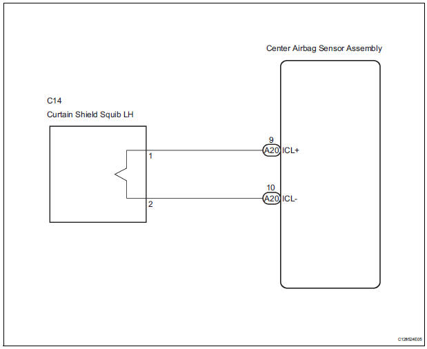
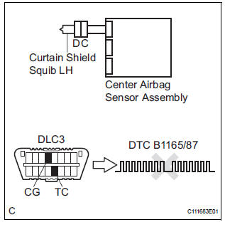
The curtain shield squib LH circuit consists of the center airbag sensor assembly and the curtain shield airbag assembly LH.
The circuit instructs the SRS to deploy when deployment conditions are met.
DTC B1165/87 is recorded when a short circuit is detected in the curtain shield squib LH circuit.
|
DTC No. |
DTC Detecting Condition |
Trouble Area |
|
B1165/87 |
|
|
WIRING DIAGRAM
INSPECTION PROCEDURE
HINT:
- Perform the simulation method by selecting the "check mode" (signal check) with the intelligent tester
- After selecting the "check mode" (signal check), perform the simulation method by wiggling each connector of the airbag system or driving the vehicle on a city or rough road
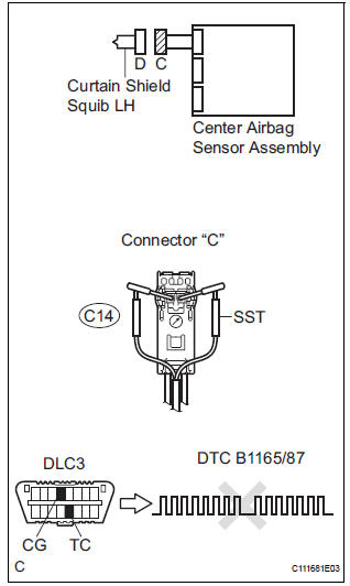
1 CHECK CURTAIN SHIELD AIRBAG ASSEMBLY LH (CURTAIN SHIELD SQUIB LH)
- Turn the ignition switch to the LOCK position.
- Disconnect the negative (-) terminal cable from the battery, and wait for at least 90 seconds.
- Disconnect the connectors from the curtain shield airbag assembly LH.
- Connect the white wire side of SST (resistance 2.1 Ω) to the floor wire.
CAUTION: Never connect a tester to the curtain shield airbag assembly LH (curtain shield squib LH) for measurement, as this may lead to a serious injury due to airbag deployment.
NOTICE: Do not forcibly insert the SST into the terminals of the connector when connecting.
Insert the SST straight into the terminals of the connector.
SST 09843-18060
- Connect the negative (-) terminal cable to the battery, and wait for at least 2 seconds.
- Turn the ignition switch to the ON position, and wait for at least 60 seconds.
- Clear the DTCs stored in memory (5).
- Turn the ignition switch to the LOCK position.
- Turn the ignition switch to the ON position, and wait for at least 60 seconds.
- Check the DTCs (5).
OK: DTC B1165/87 is not output. HINT: Codes other than DTC B1165/87 may be output at this time, but they are not related to this check.
 Go to step 2

REPLACE CURTAIN SHIELD AIRBAG ASSEMBLY LH
2 CHECK CONNECTORS
- Turn the ignition switch to the LOCK position.
- Disconnect the negative (-) terminal cable from the battery, and wait for at least 90 seconds.
- Disconnect the SST (resistance 2.1 Ω) from the floor wire.
- Check that the floor wire connectors (on the curtain shield airbag assembly LH side) are not damaged.
OK: The lock button is not disengaged, and the claw of the lock is not deformed or damaged.
 REPAIR OR REPLACE FLOOR WIRE

3 CHECK FLOOR WIRE (CURTAIN SHIELD SQUIB LH CIRCUIT)
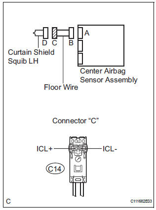
- Disconnect the connector from the center airbag sensor assembly.
- Release the activation prevention mechanism built into connector "B" (7).
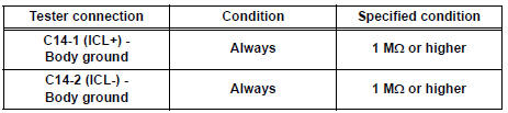
- Measure the resistance according to the value(s) in the table below.
Standard resistance
 REPAIR OR REPLACE FLOOR WIRE

4 CHECK CENTER AIRBAG SENSOR ASSEMBLY
- Connect the connectors to the curtain shield airbag assembly LH and the center airbag sensor assembly.
- Connect the negative (-) terminal cable to the battery, and wait for at least 2 seconds.
- Turn the ignition switch to the ON position, and wait for at least 60 seconds.
- Clear the DTCs stored in memory (5).
- Turn the ignition switch to the LOCK position.
- Turn the ignition switch to the ON position, and wait for at least 60 seconds.
- Check the DTCs (5).
OK: DTC B1165/87 is not output. HINT: Codes other than DTC B1165/87 may be output at this time, but they are not related to this check.
 REPLACE CENTER AIRBAG SENSOR
ASSEMBLY
REPLACE CENTER AIRBAG SENSOR
ASSEMBLY

USE SIMULATION METHOD TO CHECK
 Short to B+ in Curtain Shield Squib RH Circuit
DTC B1163/82 Short to B+ in Curtain Shield Squib RH Circuit
DESCRIPTION
The curtain shield squib RH circuit consists of the center airbag sensor
assembly and the curtain shield
airbag assembly RH ...
 Open in Curtain Shield Squib LH Circuit
DTC B1166/88 Open in Curtain Shield Squib LH Circuit
DESCRIPTION
The curtain shield squib LH circuit consists of the center airbag sensor
assembly and the curtain shield
airbag assembly LH.
Th ...
Other materials:
Bluetooth® Audio
Listening to Bluetooth® Audio
The Bluetooth® audio system enables the user to enjoy music
played on a portable player from the vehicle speakers via wireless
communication.
When a Bluetooth® device cannot be connected, check the connection
status on the “Bluetooth* Audio” screen. If the ...
Repair
1. STEERING OFF CENTER REPAIR PROCEDURE
(a) Inspect steering wheel off center.
(1) Apply masking tape to the top center of the
steering wheel and steering column upper
cover.
(2) Drive the vehicle in a straight line for 100
meters at a constant speed of 35 mph (56 km/
h), and hold the ...
Communication Error from Distance Control
ECU to ECM
DTC P1615 Communication Error from Distance Control
ECU to ECM
DTC U1101 Lost Communication with Distance Control
ECU
DESCRIPTION
The distance control ECU receives information about the area in front of the
vehicle from the laser sensor
and then sends a brake control demand signal (decelerat ...
