Toyota Sienna Service Manual: Manual Up / Down and Auto Down Function does not Operate on Passenger Side Only
DESCRIPTION
If the manual UP/DOWN function does not operate, the power window motor, the regulator switch or the wire harness may be malfunctioning.
WIRING DIAGRAM
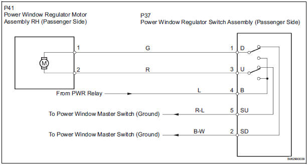
INSPECTION PROCEDURE
1 CHECK WIRE HARNESS (POWER SOURCE)
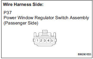
- Disconnect the P37 regulator switch connector.
- Turn the ignition switch ON.
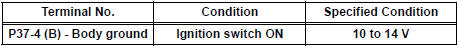
- Check the voltage between the terminal 4 of the wire harness side connector and the body ground.
Standard voltage
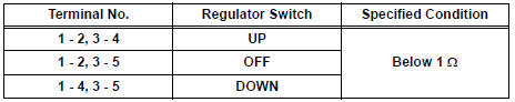
2 INSPECT FRONT PASSENGER SIDE POWER WINDOW SWITCH
- Remove the regulator switch.
- Check the resistance between the switch terminals when the switch is operated, as shown in the table below.
Standard resistance
3 CHECK WIRE HARNESS (REGULATOR SWITCH - MOTOR) (REGULATOR SWITCH - BODY GROUND)
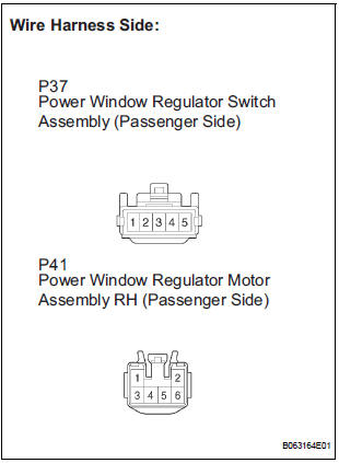
- Disconnect the P41 motor connector.
- Check the resistance between the wire harness side connectors.
Standard resistance
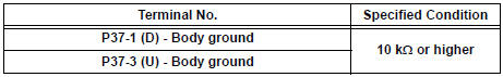
- Check the resistance between the P37 regulator switch connector and body ground.
Standard resistance
4 INSPECT POWER WINDOW REGULATOR MOTOR ASSEMBLY (PASSENGER SIDE)
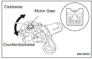
- Remove the motor.
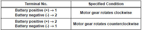
- Apply battery voltage to connector terminals 1 and 2.
- Check that the motor smoothly rotates.
NOTICE: Do not apply battery voltage to any terminals except terminals 1 and 2.
Standard
REPAIR OR REPLACE HARNESS AND CONNECTOR (MASTER SWITCH - REGULATOR SWITCH)
 Manual Up / Down and Auto Down Function does not Operate on
Driver Side
Manual Up / Down and Auto Down Function does not Operate on
Driver Side
DESCRIPTION
If the manual UP/DOWN function does not operate, no power may be supplied to
the power window
master switch or the power window motor. The power window master switch itself
or the wi ...
 Manual Up / Down Function does not Operate on Rear LH Only
DESCRIPTION
If the manual UP/DOWN function does not operate, the power window motor, the
regulator switch or the
wire harness may be malfunctioning.
WIRING DIAGRAM
INSPECTION PROCEDURE
1 CH ...
Other materials:
Checking monitor status
The purpose of the monitor result (mode 06) is to allow
access to the results for on-board diagnostic monitoring tests
of specific components/systems that are not continuously
monitored. Examples are catalyst, evaporative emission
(EVAP) and thermostat.
The monitor result allows the OBD II sc ...
Precaution
1. INSPECTION PROCEDURE FOR VEHICLE INVOLVED
IN ACCIDENT
Perform the zero point calibration and sensitivity
check if any of the following conditions occur.
The occupant classification ECU is replaced.
Accessories (seatback tray and seat cover, etc.)
are installed.
...
Correct driving posture
Adjust the angle of the seatback so that you are sitting straight up and
so that you do not have to lean forward to steer.
Adjust the seat so that you can depress the pedals fully and so that
your arms bend slightly at the elbow when gripping the steering wheel.
Lock the head rest ...
