Toyota Sienna Service Manual: Short to B+ in Side Squib LH Circuit
DTC B0118/46 Short to B+ in Side Squib LH Circuit
DESCRIPTION
The side squib LH circuit consists of the center airbag sensor assembly and the front seat side airbag assembly LH (side squib LH).
This circuit instructs the SRS to deploy when deployment conditions are met.
DTC B0118/46 is recorded when a short to B+ is detected in the side squib LH circuit
|
DTC No. |
DTC Detecting Condition |
Trouble Area |
|
B0118/46 |
|
|
INSPECTION PROCEDURE
HINT:
- Perform the simulation method by selecting the "check mode" (signal check) with the intelligent tester (8).
- After selecting the "check mode" (signal check), perform the simulation method by wiggling each connector of the airbag system or driving the vehicle on a city or rough road
1 CHECK FRONT SEAT SIDE AIRBAG ASSEMBLY LH (SIDE SQUIB LH)
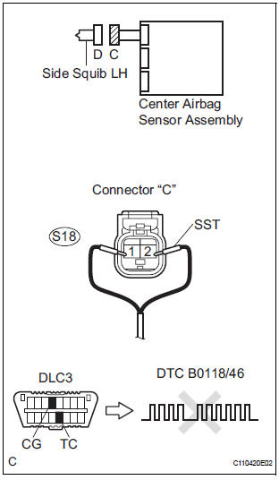
- Turn the ignition switch to the LOCK position.
- Disconnect the negative (-) terminal cable from the battery, and wait for at least 90 seconds.
- Disconnect the connectors from the front seat side airbag assembly LH.
- Connect the black wire side of SST (resistance 2.1 Ω) to the floor wire.
CAUTION: Never connect a tester to the front seat side airbag assembly LH (side squib LH) for measurement, as this may lead to a serious injury due to airbag deployment.
NOTICE: Do not forcibly insert the SST into the terminals of the connector when connecting.
Insert the SST straight into the terminals of the connector.
SST 09843-18060
- Connect the negative (-) terminal cable to the battery, and wait for at least 2 seconds.
- Turn the ignition switch to the ON position, and wait for at least 60 seconds.
- Clear the DTCs stored in memory (5).
- Turn the ignition switch to the LOCK position.
- Turn the ignition switch to the ON position, and wait for at least 60 seconds.
- Check the DTCs
OK: DTC B0118/46 is not output.
HINT: Codes other than DTC B0118/46 may be output at this time, but they are not related to this check.
 Go to step 2

REPLACE FRONT SEAT ASSEMBLY LH
2 CHECK FLOOR WIRE (SIDE SQUIB LH CIRCUIT)
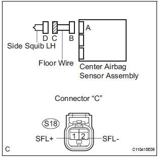
- Turn the ignition switch to the LOCK position.
- Disconnect the negative (-) terminal cable from the battery, and wait for at least 90 seconds.
- Disconnect the SST (resistance 2.1 Ω) from the floor wire.
- Disconnect the connector from the center airbag sensor assembly.
- Connect the negative (-) terminal cable to the battery, and wait for at least 2 seconds.
- Turn the ignition switch to the ON position.
- Measure the voltage according to the value(s) in the table below.
Standard voltage
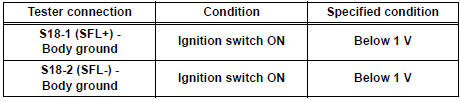
 REPAIR OR REPLACE FLOOR WIRE

3 CHECK CENTER AIRBAG SENSOR ASSEMBLY
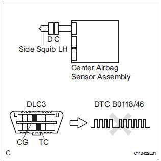
- Turn the ignition switch to the LOCK position.
- Disconnect the negative (-) terminal cable from the battery, and wait for at least 90 seconds.
- ) Connect the connectors to the front seat side airbag assembly LH and the center airbag sensor assembly.
- Connect the negative (-) terminal cable to the battery, and wait for at least 2 seconds.
- Turn the ignition switch to the ON position, and wait for at least 60 seconds.
- Clear the DTCs stored in memory (5).
- Turn the ignition switch to the LOCK position.
- Turn the ignition switch to the ON position, and wait for at least 60 seconds.
- Check the DTCs (5).
OK: DTC B0118/46 is not output. HINT: Codes other than code B0118/46 may be output at this time, but they are not related to this check
 REPLACE CENTER AIRBAG SENSOR
ASSEMBLY
REPLACE CENTER AIRBAG SENSOR
ASSEMBLY

USE SIMULATION METHOD TO CHECK
 Short to GND in Side Squib LH Circuit
DTC B0117/45 Short to GND in Side Squib LH Circuit
DESCRIPTION
The side squib LH circuit consists of the center airbag sensor assembly and
the front seat side airbag
assembly LH.
This circuit ...
 Seat Belt Buckle Switch LH Circuit Malfunction
DTC B0126/27 Seat Belt Buckle Switch LH Circuit Malfunction
DESCRIPTION
The seat belt buckle switch LH circuit consists of the center airbag sensor
assembly and the front seat
inner belt assembly ...
Other materials:
Yaw rate sensor check (when using intelligent tester)
(a) Check the output of the yaw rate sensor.
(1) Move the shift lever to the D position, drive the
vehicle at a speed of approximately 5 km/h (3
mph), and turn the steering wheel either to the
left or right 90° or more until the vehicle makes a
180° turn.
(2) Stop the vehicle and mov ...
Short in Driver Side Squib Circuit
DTC B0100/13 Short in Driver Side Squib Circuit
DESCRIPTION
The driver side squib circuit consists of the center airbag sensor assembly,
the spiral cable and the
steering pad. The circuit instructs the SRS to deploy when deployment conditions
are met. DTC B0100/13
is recorded when a short ci ...
Unmatched Encryption Code
DTC B2794 Unmatched Encryption Code
DESCRIPTION
This DTC is output when a key with an incomplete key code is inserted into
the ignition key cylinder.
DTC No.
DTC Detection Condition
Trouble Area
B2794
Key with incomplete key code inserted
Key
IN ...
