Toyota Sienna Service Manual: Short to GND in Side Squib LH Circuit
DTC B0117/45 Short to GND in Side Squib LH Circuit
DESCRIPTION
The side squib LH circuit consists of the center airbag sensor assembly and the front seat side airbag assembly LH.
This circuit instructs the SRS to deploy when deployment conditions are met.
DTC B0117/45 is recorded when a short to ground is detected in the side squib LH circuit.
|
DTC No. |
DTC Detecting Condition |
Trouble Area |
|
B0117/45 |
|
|
INSPECTION PROCEDURE
HINT:
- Perform the simulation method by selecting the "check mode" (signal check) with the intelligent tester (8).
- After selecting the "check mode" (signal check), perform the simulation method by wiggling each connector of the airbag system or driving the vehicle on a city or rough road
1 CHECK FRONT SEAT SIDE AIRBAG ASSEMBLY LH (SIDE SQUIB LH)
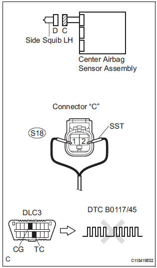
- Turn the ignition switch to the LOCK position.
- Disconnect the negative (-) terminal cable from the battery, and wait for at least 90 seconds.
- Disconnect the connectors from the front seat side airbag assembly LH.
- Connect the black wire side of SST (resistance 2.1 Ω) to the floor wire.
CAUTION: Never connect a tester to the front seat side airbag assembly LH (side squib LH) for measurement, as this may lead to a serious injury due to airbag deployment.
NOTICE: Do not forcibly insert the SST into the terminals of the connector when connecting.
Insert the SST straight into the terminals of the connector.
SST 09843-18060
- Connect the negative (-) terminal cable to the battery, and wait for at least 2 seconds.
- Turn the ignition switch to the ON position, and wait for at least 60 seconds.
- Clear the DTCs stored in memory (5).
- Turn the ignition switch to the LOCK position.
- Turn the ignition switch to the ON position, and wait for at least 60 seconds.
- Check the DTCs
OK: DTC B0117/45 is not output.
HINT: Codes other than DTC B0117/45 may be output at this time, but they are not related to this check
 Go to step 2

REPLACE FRONT SEAT ASSEMBLY LH
2 CHECK FLOOR WIRE (SIDE SQUIB LH CIRCUIT)
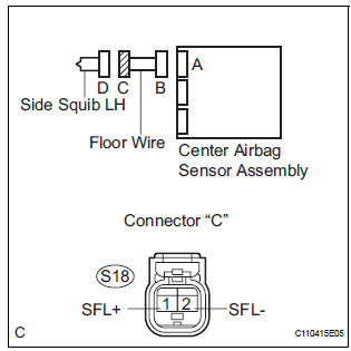
- Turn the ignition switch to the LOCK position.
- Disconnect the negative (-) terminal cable from the battery, and wait for at least 90 seconds.
- Disconnect the SST (resistance 2.1 Ω) from the floor wire.
- Disconnect the connector from the center airbag sensor assembly.
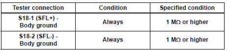
- Measure the resistance according to the value(s) in the table below.
Standard resistance
 REPAIR OR REPLACE FLOOR WIRE

3 CHECK CENTER AIRBAG SENSOR ASSEMBLY
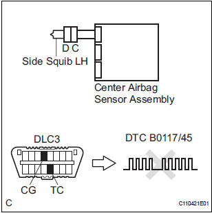
- Connect the connectors to the front seat side airbag assembly LH and the center airbag sensor assembly.
- Connect the negative (-) terminal cable to the battery, and wait for at least 2 seconds.
- Turn the ignition switch to the ON position, and wait for at least 60 seconds.
- Clear the DTCs stored in memory (5).
- Turn the ignition switch to the LOCK position.
- Turn the ignition switch to the ON position, and wait for at least 60 seconds.
- Check the DTCs (5).
OK: DTC B0117/45 is not output.
HINT: Codes other than code B0117/45 may be output at this time, but they are not related to this check.
 REPLACE CENTER AIRBAG SENSOR
ASSEMBLY
REPLACE CENTER AIRBAG SENSOR
ASSEMBLY

USE SIMULATION METHOD TO CHECK
 Open in Side Squib LH Circuit
DTC B0116/48 Open in Side Squib LH Circuit
DESCRIPTION
The side squib LH circuit consists of the center airbag sensor assembly and
the front seat side assembly
LH.
This circuit instructs the S ...
 Short to B+ in Side Squib LH Circuit
DTC B0118/46 Short to B+ in Side Squib LH Circuit
DESCRIPTION
The side squib LH circuit consists of the center airbag sensor assembly and
the front seat side airbag
assembly LH (side squib LH).
...
Other materials:
Fuel Pump Primary Circuit
DESCRIPTION
This DTC is designed to detect a malfunction in the fuel pump (FUEL
PUMP) relay circuit. When the
system is normal, the battery voltage is applied to FPR terminal of the ECM
while the FUEL PUMP
relay is turned OFF. If the battery voltage is not applied to the FPR
ter ...
Removal
1. RECOVER REFRIGERANT FROM REFRIGERATION
SYSTEM (See page AC-172)
2. REMOVE NO. 2 AIR CLEANER INLET (See page EM-
28)
3. REMOVE FRONT BUMPER ASSEMBLY (See page
ET-3)
4. DISCONNECT DISCHARGE HOSE SUB-ASSEMBLY
(a) Remove the bolt and disconnect the discharge hose
sub-assembly from the coo ...
Removal
HINT:
Remove the RH side by the same procedure as the LH side.
1. REMOVE REAR WHEEL
2. DRAIN BRAKE FLUID
NOTICE:
Wash the brake fluid off immediately if it attaches to
any painted surface.
3. SEPARATE REAR BRAKE TUBE NO.4
(a) Remove the clip and a disconnect, the rear brake
flexible hos ...
