Toyota Sienna Service Manual: Short to GND in Rear Curtain Shield Squib LH Circuit
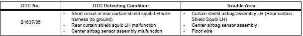
DTC B1637/85 Short to GND in Rear Curtain Shield Squib LH Circuit
DESCRIPTION
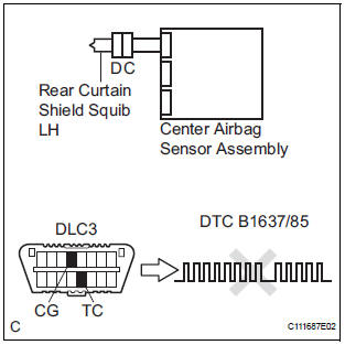
The rear curtain shield squib LH circuit consists of the center airbag sensor assembly and the curtain shield airbag assembly LH.
The circuit instructs the SRS to deploy when deployment conditions are met.
DTC B1637/85 is recorded when a short to ground is detected in the rear curtain shield squib LH circuit
WIRING DIAGRAM
INSPECTION PROCEDURE
HINT:
- Perform the simulation method by selecting the "check mode" (signal check) with the intelligent tester.
- After selecting the "check mode" (signal check), perform the simulation method by wiggling each connector of the airbag system or driving the vehicle on a city or rough road
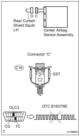
1 CHECK CURTAIN SHIELD AIRBAG ASSEMBLY LH (REAR CURTAIN SHIELD SQUIB LH)
- Turn the ignition switch to the LOCK position.
- Disconnect the negative (-) terminal cable from the battery, and wait for at least 90 seconds.
- Disconnect the connectors from the curtain shield airbag assembly LH.
- Connect the white wire side of SST (resistance 2.1 Ω) to
the floor wire.
CAUTION: Never connect a tester to the curtain shield airbag assembly LH (Rear curtain shield squib LH) for measurement, as this may lead to a serious injury due to airbag deployment.
NOTICE: Do not forcibly insert the SST into the terminals of the connector when connecting.
Insert the SST straight into the terminals of the connector.
SST 09843-18060
- Connect the negative (-) terminal cable to the battery, and wait for at least 2 seconds.
- Turn the ignition switch to the ON position, and wait for at least 60 seconds.
- Clear the DTCs stored in memory.
- Turn the ignition switch to the LOCK position.
- Turn the ignition switch to the ON position, and wait for at least 60 seconds.
- Check the DTCs.
OK: DTC B1637/85 is not output.
HINT: Codes other than DTC B1637/85 may be output at this time, but they are not related to this check.
REPLACE CURTAIN SHIELD AIRBAG ASSEMBLY LH
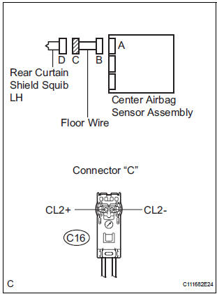
2 CHECK FLOOR WIRE (REAR CURTAIN SHIELD SQUIB LH CIRCUIT)
- Turn the ignition switch to the LOCK position.
- Disconnect the negative (-) terminal cable from the battery, and wait for at least 90 seconds.
- Disconnect the SST (resistance 2.1 Ω) from the floor wire.
- Disconnect the connector from the center airbag sensor assembly.
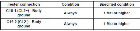
- Measure the resistance according to the value(s) in the table below.
Standard resistance
3 CHECK CENTER AIRBAG SENSOR ASSEMBLY
- Connect the connectors to the curtain shield airbag assembly LH and the center airbag sensor assembly.
- Connect the negative (-) terminal cable to the battery, and wait for at least 2 seconds.
- Turn the ignition switch to the ON position, and wait for at least 60 seconds.
- Clear the DTCs stored in memory.
- Turn the ignition switch to the LOCK position.
- Turn the ignition switch to the ON position, and wait for at least 60 seconds.
- Check the DTCs.
OK: DTC B1637/85 is not output.
HINT: Codes other than code B1637/85 may be output at this time, but they are not related to this check
USE SIMULATION METHOD TO CHECK
 Open in Rear Curtain Shield Squib LH Circuit
DTC B1636/88 Open in Rear Curtain Shield Squib LH Circuit
DESCRIPTION
The rear curtain shield squib LH circuit consists of the center airbag sensor
assembly and the curtain
shield airbag assembly ...
 Short to B+ in Rear Curtain Shield Squib LH
Circuit
Short to B+ in Rear Curtain Shield Squib LH
Circuit
DTC B1638/86 Short to B+ in Rear Curtain Shield Squib LH
Circuit
DESCRIPTION
The rear curtain shield squib LH circuit consists of the center airbag sensor
assembly and the curtain
shield airbag ...
Other materials:
DRL Relay Circuit
DESCRIPTION
The Multiplex network body ECU controls the DRL No.2 relay
WIRING DIAGRAM
INSPECTION PROCEDURE
1 PERFORM ACTIVE TEST BY INTELLIGENT TESTER
Connect the intelligent tester to DLC3.
Turn the ignition switch ON and push the intelligent
tester main switch ON.
Sel ...
Correct use of the seat belts
Extend the shoulder belt so that
it comes fully over the shoulder,
but does not come into contact
with the neck or slide off the
shoulder.
Position the lap belt as low as
possible over the hips.
Adjust the position of the seatback.
Sit up straight and well
back in the seat.
...
No Master/ Connection Check Error
DTC 01-D6 No Master
DTC 01-D7 Connection Check Error
DESCRIPTION
DTC No.
DTC Detection Condition
Trouble Area
01-D6
*1
When either of the following conditions is met:
The component which has stored the code has
(had) been disconnected when the ...
