Toyota Sienna Service Manual: DRL Relay Circuit
DESCRIPTION
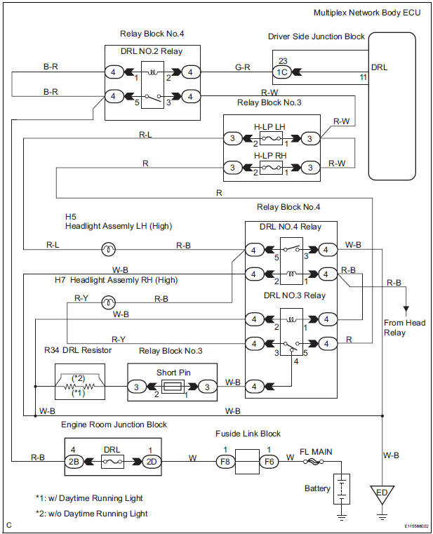
The Multiplex network body ECU controls the DRL No.2 relay
WIRING DIAGRAM
INSPECTION PROCEDURE
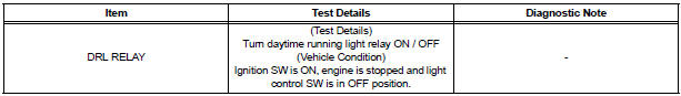
1 PERFORM ACTIVE TEST BY INTELLIGENT TESTER
- Connect the intelligent tester to DLC3.
- Turn the ignition switch ON and push the intelligent tester main switch ON.
- Select the item below in the ACTIVE TEST and then check that the relay operates.
BODY NO.1:
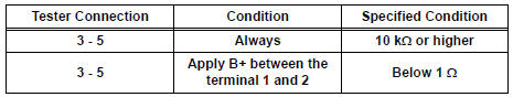
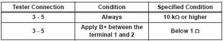
2 INSPECT DRL NO.2 RELAY
- Inspect DRL No.2 Relay continuity.
Resistance
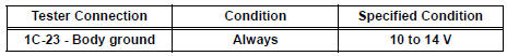
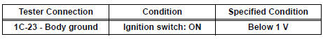
3 CHECK HARNESS AND CONNECTOR (POWER SOURCE)
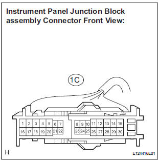
- Disconnect the connector from the instrument panel junction block assembly.
- Measure the voltage according to the value(s) in the table below.
Voltage
4 INSPECT INSTRUMENT PANEL JUNCTION BLOCK ASSEMBLY
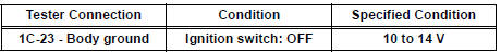
- Reconnect the connector to the instrument panel junction block assembly.
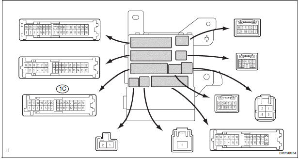
- Measure the voltage according to the value(s) in the table below.
Voltage
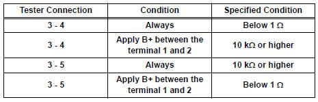
5 INSPECT RELAY (DRL NO.3, DRL NO.4)
- Inspect DRL NO.4 Relay continuity.
Resistance
- Inspect DRL NO.3 Relay continuity.
Resistance
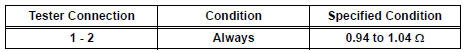
6 INSPECT DAYTIME RUNNING LIGHT RESISTER
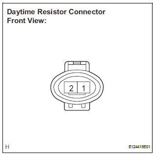
- Measure the resistance according to the value(s) in the table below.
Resistance
REPAIR OR REPLACE HARNESS OR CONNECTOR
 Headlight Relay Circuit
DESCRIPTION
The Multiplex network body ECU controls HEAD relay when signal is received
from headlight dimmer
switch assembly.
WIRING DIAGRAM
INSPECTION PROCEDURE
1 PERFORM ACTIVE TEST BY IN ...
 Front Fog Light Circuit
DESCRIPTION
The Multiplex network body ECU controls FOG relay when signal is received
from headlight dimmer
switch assembly.
WIRING DIAGRAM
INSPECTION PROCEDURE
1 PERFORM ACTIVE TEST BY INT ...
Other materials:
Reassembly
1. INSTALL NO. 1 SEAT CUSHION FRAME SUBASSEMBLY
Install the seat cushion frame with the bolt.
Torque: 20.6 N*m (210 kgf*cm, 15 ft.*lbf)
2. INSTALL RECLINING CONTROL LINK SUBASSEMBLY
Install the reclining control link with the E-ring.
Install the nut.
3. INSTALL RE ...
Front Occupant Classification Sensor RH Circuit
Malfunction
DTC B1781 Front Occupant Classification Sensor RH Circuit
Malfunction
DESCRIPTION
The front occupant classification sensor RH circuit consists of the occupant
classification ECU and the
front occupant classification sensor RH.
DTC B1781 is recorded when a malfunction is detected in the fron ...
Cranking Holding Function Circuit
DESCRIPTION
The system detects the ignition switch's starting signal (STSW) and then
supplies current to the starter
until the ECM judges that the engine has started successfully. The purpose is to
reduce the holding time
of the ignition key.
WIRING DIAGRAM
Refer to DTC P0617.
INSPECTI ...
