Toyota Sienna Service Manual: Terminals of ecu
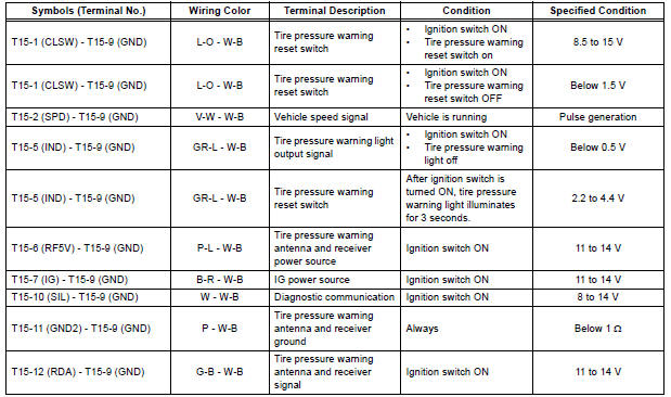
Check tire pressure warning ecu
HINT: Inspect the connectors from the back side while the connectors are connected.

(a) Disconnect the tire pressure warning antenna and receiver connector.
(b) Measure the voltage according to the value(s) in the table below.

(c) Connect the tire pressure warning antenna and receiver connector.
(d) Measure the voltage and resistance according to the value(s) in the table below. If the result is not as specified, the ECU may have a malfunction.

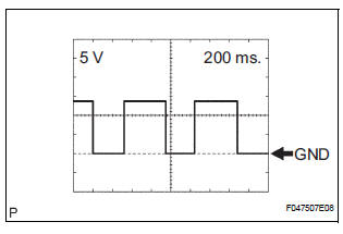
(e) Using an oscilloscope, check the waveform 1.
(1) Waveform 1 (Reference)

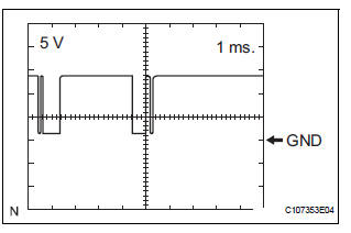
(2) Waveform 2 (Reference)
 Problem symptoms table
HINT:
Use the table below to help determine the cause of the
problem symptom. The potential causes of the symptoms
are listed in order of probability in the "Suspected Area"
column ...
 Diagnosis system
1. CHECK BATTERY VOLTAGE
Standard voltage:
11 to 14 V
If the voltage is below 11 V, recharge the battery before
proceeding.
2. CHECK DLC3
(a) The ECU uses the ISO 15765-4 for communication
pr ...
Other materials:
Customize parameters
1. CUSTOMIZING FUNCTION WITH INTELLIGENT
TESTER (REFERENCE)
HINT:
The following items can be customized.
NOTICE:
After confirming whether the items requested by
the customer are applicable or not for
customization, perform customize operations.
Be sure to record the current ...
Open in Curtain Shield Squib LH Circuit
DTC B1166/88 Open in Curtain Shield Squib LH Circuit
DESCRIPTION
The curtain shield squib LH circuit consists of the center airbag sensor
assembly and the curtain shield
airbag assembly LH.
The circuit instructs the SRS to deploy when deployment conditions are met.
DTC B1166/88 is recorde ...
Inspection procedure
1 BASIC INSPECTION
Check the conditions necessary for the power slide door
to open:
Power slide door main switch is in the ON position
(switch free: orange paint on the top of the switch
appears).
Slide door is unlocked (door lock position switch is
in the ON position when ...
