Toyota Sienna Service Manual: Precaution
1. HANDLING PRECAUTION FOR CRUISE CONTROL SYSTEM
- Turn the cruise control main switch off when not using the cruise control system.
- Be careful as the vehicle speed increases when driving downhill with the cruise control system on.
- The + (ACCEL)/RES (RESUME) operation changes according to the cruise control system status. When the cruise control system is operating, the + (ACCEL) function operates. When the cruise control system is not operating, the RES (RESUME) function operates.
- If the CRUISE main indicator light blinks while the cruise control system is operating, turn the cruise control main switch off to reset the cruise control system. After the reset, if the cruise control main switch cannot be turned on, or the cruise control system is canceled immediately after turning the cruise control main switch on, the system may have a malfunction.
- Do not use the cruise control system where the road conditions are as follows:
- Heavy traffic
- Steep decline
- Roads with sharp turns
- Icy or snowy roads
- Slippery roads
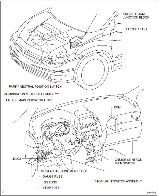
PARTS LOCATION
SYSTEM DIAGRAM
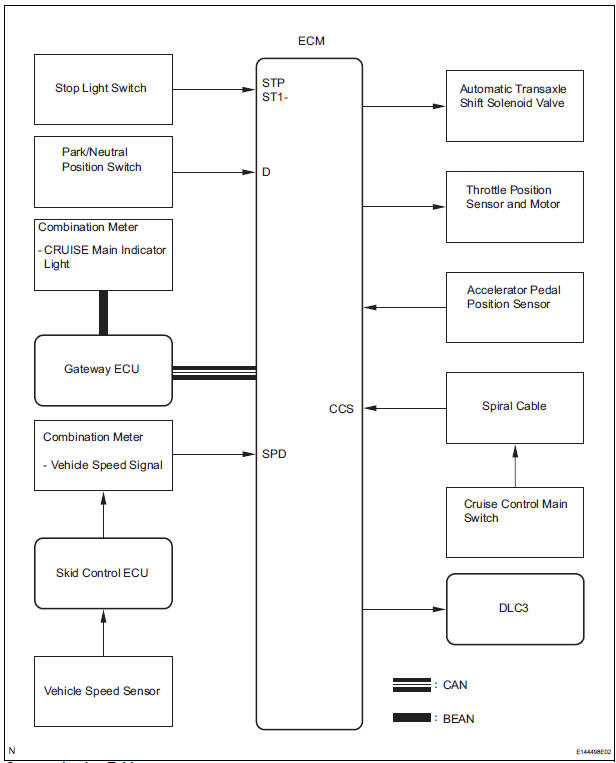
Communication Table:


 System description
1. CRUISE CONTROL SYSTEM
This system is controlled by the ECM, and is activated by
the throttle position sensor and motor. The ECM controls
the following functions: ON-OFF, - (COAST)/SET, +
(ACCEL ...
Other materials:
Rear view monitor
system
The rear view monitor system assists the driver by displaying an
image of the view behind the vehicle and guide lines while backing
up, for example while parking.
The screen illustrations used in this text are intended as examples,
and may differ from the image that is actually displayed on the
...
Replacing light bulbs
Headlight low beams (halogen bulb)
For left side only: Open the fuse box cover.
Unplug the connector while
pushing the lock release.
Turn the bulb base counterclockwise.
Install a new light bulb.
Align the 3 tabs on the light bulb
with the mounting, and insert.
...
Removal
1. BOLT, SCREW AND NUT TABLE
The bolts, the screws and the nuts, which are
necessary for installation and removal of the
instrument panel are shown in the illustration below
with alphabets.
2. DISCONNECT BATTERY NEGATIVE TERMINAL
3. REMOVE STEERING WHEEL COVER LOWER NO.2
4. ...
