Toyota Sienna Service Manual: Camera Picture Error
DTC 5C-40 Camera Picture Error
DESCRIPTION
|
DTC No. |
DTC Detection Condition |
Trouble Area |
|
5C-40 |
Synchronous signal from the camera cannot be transmitted. |
|
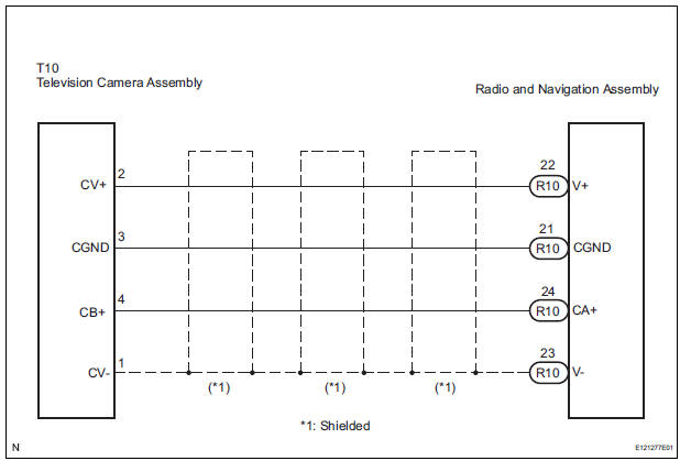
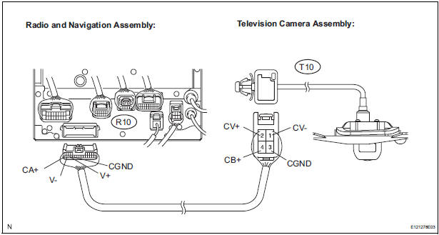
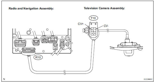
WIRING DIAGRAM
INSPECTION PROCEDURE
HINT: After the inspection is completed, clear the DTCs.
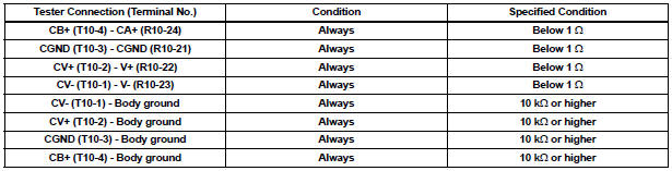
1 CHECK HARNESS AND CONNECTOR (RADIO AND NAVIGATION ASSEMBLY - TELEVISION CAMERA ASSEMBLY)
- Disconnect the R10 connector from the radio and navigation assembly.
- Disconnect the T10 connector from the television camera assembly.
- Measure the resistance according to the value(s) in the table below.
Standard resistance
2 INSPECT RADIO AND NAVIGATION ASSEMB
- Reconnect the radio and navigation assembly connector.
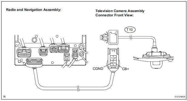
- Measure the voltage according to the value(s) in the table below.
Standard voltage

3 INSPECT TELEVISION CAMERA ASSEMBLY
- Reconnect the radio and navigation assembly R10 connector and the television camera assembly T10 connector
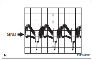
- Check the waveform of the television camera assembly using an oscilloscope.
- Measurement terminal: CV+ - CVMeasurement setting: 0.2 V/DIV, 0.2 μs/DIV Condition: Ignition switch ON, Shift lever in R range
OK: Pulses as shown in the illustration.
REPLACE RADIO AND NAVIGATION ASSEMBLY
 High Temperature
DTC 58-45 High Temperature
DTC 80-45 High Temperature
DESCRIPTION
DTC No.
DTC Detection Condition
Trouble Area
58-45
High map disc player temperature is det ...
 CD Changer Mechanical Error/ CD Insertion and Ejection Error/ CD Reading
Abnormal
CD Changer Mechanical Error/ CD Insertion and Ejection Error/ CD Reading
Abnormal
DTC 63-10 CD Changer Mechanical Error
DTC 63-11 CD Insertion and Ejection Error
DTC 63-12 CD Reading Abnormal
DESCRIPTION
DTC No.
DTC Detection Condition
Trouble Area
...
Other materials:
Display settings
Settings are available for adjusting the contrast and brightness
of the screen.
Screen for display settings
Press the “SETUP” button.
Select “Display” on the “Setup” screen.
Adjust screen contrast/brightness
Adjust screen contrast/brightness
of the rear view monitor ...
Fail-safe chart
1. AUTO CANCEL FUNCTION (FAIL-SAFE FUNCTION):
HINT:
If a system malfunction occurs, the applicable DTCs will
appear on the multi-information display. In some cases,
a DTC will be set due to weather or vehicle operating
conditions, this does not indicate a system malfunction.
E3 (i ...
Installation
1. INSTALL REAR NO. 1 SEAT ASSEMBLY LH
Place the seat in the cabin.
NOTICE:
Be careful not to damage the body.
Install the seat.
7-Passenger RH:
Install the seat belt anchor plate with the bolt.
Torque: 42 N*m (428 kgf*cm, 31 ft.*lbf)
Install the headrest. ...
