Toyota Sienna 2010-2026 Owners Manual: Turning the high beam on/off manually
Switching to low beam
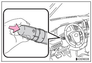
Pull the lever to the original position.
Switching to high beam
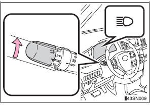
Turn the light switch to the
 position.
The Automatic High Beam can be operated when
The engine switch is in the “ON” position (vehicles without a smart key system) or IGNITION ON mode (vehicles with a smart key system).
Camera sensor detection information
- High beam may not be automatically turned off in the following situations:
- When oncoming vehicles suddenly appear from a curve.
- When the vehicle is cut in front of by another.
- High beam may be turned off if an oncoming vehicle that is using fog lights without using the headlights is detected.
- Houselights, streetlights, red traffic signals, and illuminated billboards or signs may cause the high beam to turn off.
- The following factors may affect the amount of time taken to turn high beam on or off:
- The brightness of headlights, fog lights, and tail lights of oncoming and preceding vehicles
- Road conditions (wetness, ice, snow etc.)
- The number of passengers and amount of baggage
- High beam may be turned on or off when unexpected by the driver.
- In the situations below, the system may not be able to correctly detect the surrounding brightness levels, and may flash or expose nearby pedestrians to the high beam. Therefore, you should consider turning the high beam on or off manually rather than relying on the Automatic High Beam system.
- In bad weather (rain, snow, fog, sandstorms etc.)
- The windshield is obscured by fog, mist, ice, dirt etc.
- The windshield is cracked or damaged.
- The camera sensor is deformed or dirty.
- Surrounding brightness levels are equal to those of headlights, tail lights or fog lights.
- Vehicles ahead have headlights that are either switched off, dirty, are changing color, or are not aimed properly.
- When driving through an area of intermittently changing brightness and darkness
- When frequently and repeatedly driving ascending/descending roads, or roads with rough, bumpy or uneven surfaces (such as stone-paved roads, gravel tracks etc.)
- When frequently and repeatedly taking curves or driving on a winding road
- There is a highly reflective object ahead of the vehicle, such as a sign or a mirror.
- The vehicle’s headlights are damaged or dirty.
- The vehicle is lifting or tilting, due to a flat tire, a trailer being towed etc.
- The high beam and low beam are repeatedly being switched between in an abnormal manner.
- The driver believes that the high beam may be causing problems or distress to other drivers or pedestrians nearby.
When the warning message is shown on the multi-information display
Temporary lowering sensor sensitivity
The sensitivity of the sensor can be temporarily lowered.
To lower the sensitivity, push and hold
 on the inside rear view mirror for
15 to 20 seconds, and release. The indicator light on the inside rear view
mirror
will flash to indicate that the sensitivity has been lowered.
When the engine switch is turned to the “LOCK” position (vehicles without a smart key system) or turned off (vehicles with a smart key system), the sensitivity will be returned to its normal level.
Customization
The Automatic High Beam can be turned off.
(Customizable features: )
| WARNING Limitations of the Automatic High Beam Do not rely on the Automatic High Beam. Always drive safely, taking care to observe your surroundings and turning high beam on or off manually if necessary. |
| NOTICE Camera sensor
Observe the following to ensure that the Automatic High Beam functions correctly.
Headlight leveling When the vehicle is loaded, headlight level should be adjusted to appropriate dial setting. |
 High beam automatic turning on or off conditions
When all of the following conditions are fulfilled, high beam will be
automatically turned on (after approximately 1 second):
Vehicle speed is above approximately 20 mph (32 km/h).
The area ahe ...
 Fog light switch
The fog lights secure excellent visibility in difficult driving
conditions,
such as in rain and fog.
The illustration is intended as an example.
Turns the fog lights on
*1 or
*2
Tur ...
Other materials:
Stop light switch
ON-VEHICLE INSPECTION
1. STOP LIGHT SWITCH ASSEMBLY
Check the resistance between the terminals at each
switch position as shown ion the chart.
Resistance
...
Stowing the third seats (power seats)
You can operate the power third seats when the shift lever is in P.
Before stowing or returning third seat, remove any items from the floor
area to prevent interference with moving parts.
Before stowing the third seats
Lower the center head
restraint to the lowest position and stow th ...
On-vehicle inspection
1. CHECK SEAT HEATER CONTROL (WIRE HARNESS
SIDE)
Disconnect the connector from the seat heater
control.
Measure the voltage and resistance of each
terminal of the wire harness side connector.
Standard
If the result is not as specified, there may be a
malfunction on ...
