Toyota Sienna Service Manual: Skid Control Buzzer Circuit
DESCRIPTION
The skid control buzzer sounds and SLIP indicator blinking during VSC operation.
WIRING DIAGRAM
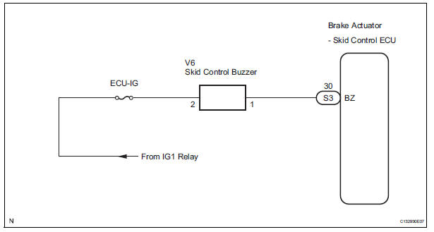
INSPECTION PROCEDURE
1 PERFORM ACTIVE TEST USING INTELLIGENT TESTER (SKID CONTROL BUZZER)
(a) Connect the intelligent tester to the DLC3.
(b) Start the engine.
(c) Select the item "VSC / BR WARN BUZ" in the ACTIVE TEST and operate the skid control buzzer on the intelligent tester.
ABS / VSC: 
(d) Check that skid control buzzer sounds by operating with the intelligent tester.
OK: The skid control buzzer sounds in accordance with operation of the intelligent tester.

REPLACE BRAKE ACTUATOR ASSEMBLY
2 INSPECT SKID CONTROL BUZZER
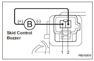
(a) Disconnect the skid control buzzer connector.
(b) Apply battery negative voltage to terminal 1, and battery positive voltage to terminal 2 of the skid control buzzer connector, and check that the buzzer sounds.
OK: The skid control buzzer sound should be heard.


3 CHECK HARNESS AND CONNECTOR (SKID CONTROL BUZZER - SKID CONTROL ECU)
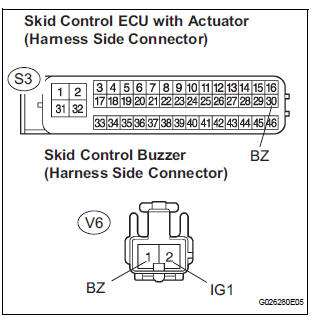
(a) Disconnect the skid control buzzer connector and the skid control ECU connector.
(b) Measure the resistance according to the value(s) in the table below.
Standard resistance 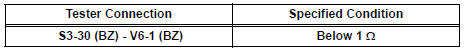
(c) Measure the resistance according to the value(s) in the table below.
Standard resistance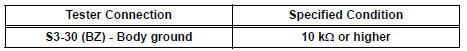
NOTICE: When replacing the brake actuator assembly, perform zero point calibration (See page BC-70)
REPLACE BRAKE ACTUATOR ASSEMBLY
 Slip Indicator Light does not Come ON
DESCRIPTION
The skid control ECU is connected to the combination meter via CAN and
multiplex communications.
The SLIP indicator blinks during VSC and/or TRAC operation.
When the system fails, ...
 TC and CG Terminal Circuit
DESCRIPTION
Connecting terminals TC and CG of the DLC3 causes the ECU to display the DTC
by blinking the ABS
warning light and/or VSC warning light.
WIRING DIAGRAM
INSPECTION PROCEDURE
NOTI ...
Other materials:
Operation check
NOTICE:
Inspection should be started after conforming that the
items listed in the "CUSTOMIZE PARAMETER" for the
power slide door system have defaulted to the initial
settings.
1. CHECK OPENING OPERATION
Conditions necessary for the power slide door to
open:
Power slid ...
Check mode procedure
HINT:
Intelligent tester only:
Compared to normal mode, check mode is more sensitive to
malfunctions. Therefore, check mode can detect the
malfunctions that cannot be detected by normal mode.
NOTICE:All the stored DTCs and freeze frame data are
erased if:
1) the ECM is changed fro ...
Installation
1. INSTALL BRAKE ACTUATOR
(a) Install the brake actuator assembly with the 2 nuts.
Torque: 5.4 N*m (55 kgf*cm, 48 in.*lbf)
2. INSTALL BRAKE ACTUATOR WITH BRACKET
(a) Install the actuator with bracket with the 3 bolts.
Torque: 20 N*m (199 kgf*cm, 14 ft.*lbf)
NOTICE:
Be careful not to dam ...
